Capacitive micro-machined ultrasound transducer device with charging voltage source

a micro-machined, ultrasound transducer technology, applied in the direction of transducer types, mechanical vibration separation, instruments, etc., can solve the problems of limiting the operating bias voltage that can be applied, the efficiency and acoustic pressure output of the current cmut device relative to the existing piezoelectric transducer device, and the limitations of the operating bias voltage, so as to reduce the cost of the device, increase the flexibility of the device, and high output pressure

Active Publication Date: 2015-01-15
KONINKLJIJKE PHILIPS NV
View PDF3 Cites 13 Cited by
  • Summary
  • Abstract
  • Description
  • Claims
  • Application Information

AI Technical Summary

Benefits of technology

[0026]In another embodiment, the CMUT device is a high-intensity focused ultrasound (HIFU) transducer device. In this way the charging effect can be used in an optimal way, because a high output pressure is required in an HIFU transducer device. A HIFU transducer device can for example be used in a medical system to heat and destroy pathogenic tissue rapidly through ablation.
[0027]In a further embodiment, the operating bias voltage source and the charging voltage source are implemented in one single voltage source. This reduces costs of the device. In an alternative embodiment, the bias voltage source and the charging voltage source are implemented as separate voltage sources. This increases flexibility of the device. For example, two different voltage levels can be implemented in this way.

Problems solved by technology

However, CMUT devices currently may still have a disadvantage in terms of the efficiency and acoustic pressure output relative to existing piezoelectric transducer devices.
However, there are limits to the operating bias voltage that can be applied due to dielectric breakdown and charged tunneling effects.
There may also be limits to the operating bias voltage due to driving circuitry, for example in the form of an application specific integrated circuit (ASIC).
A problem with applying an increased or excessive operating bias voltage can be that the membrane collapses to the substrate and thereby the electrodes may electrically contact each other.
It is a currently recognized limitation of CMUT device that if excessive operating bias voltages are applied to the device, the dielectric layers used to separate the electrodes can become more or less permanently charged.
This charging effect has been recognized and deemed a problem or “reliability issue” and an undesirable side effect of the construction of the device.
In particular, the permanent charge of the dielectric layers reduces the efficiency of the device as an acoustic transducer device.

Method used


Image

  • Capacitive micro-machined ultrasound transducer device with charging voltage source
  • Capacitive micro-machined ultrasound transducer device with charging voltage source
  • Capacitive micro-machined ultrasound transducer device with charging voltage source

Examples


Embodiment Construction

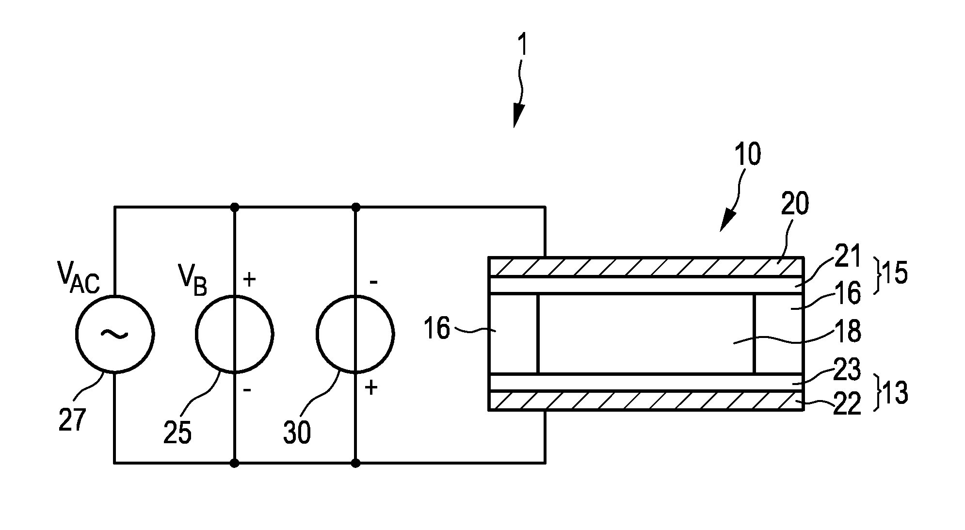
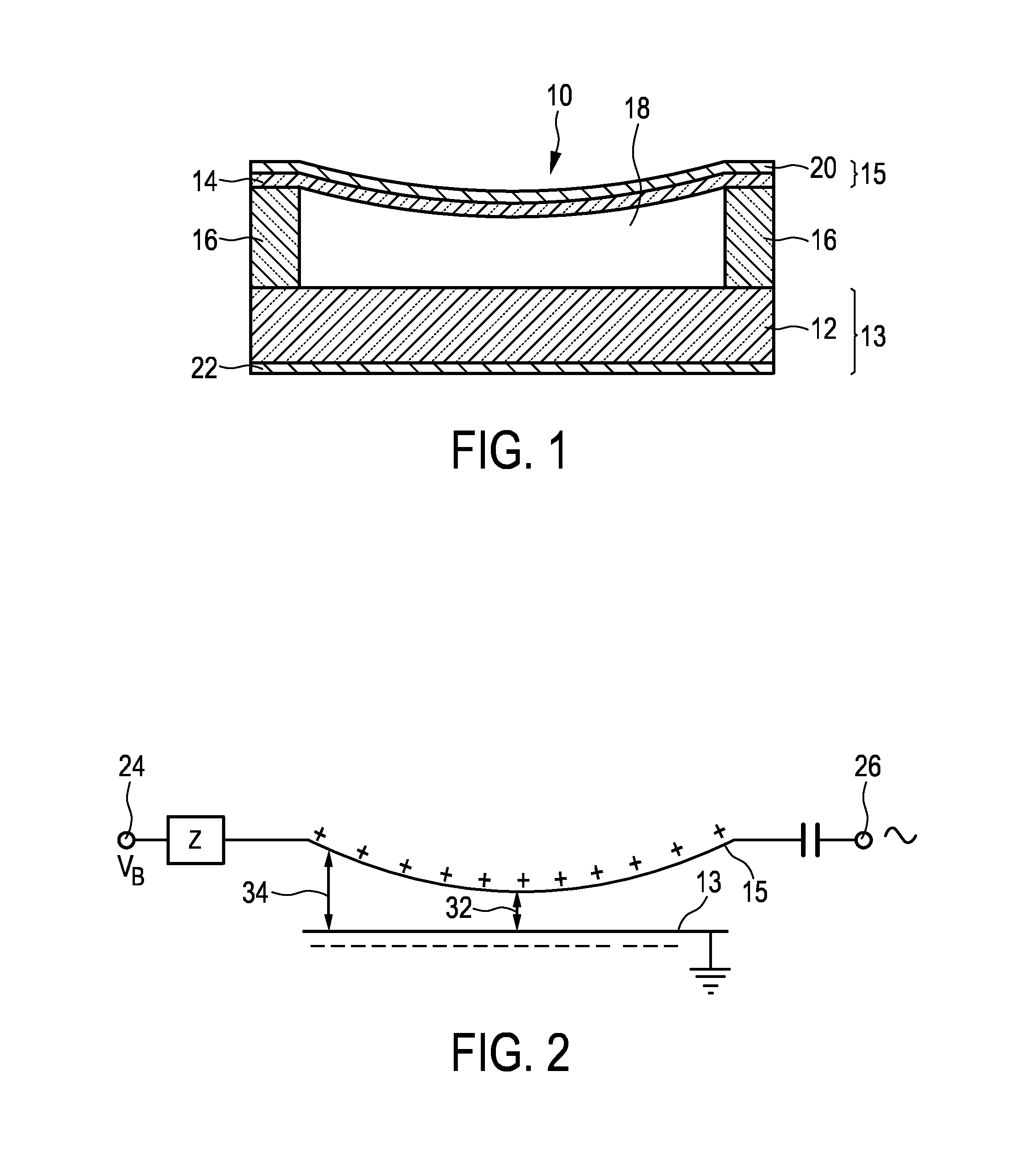
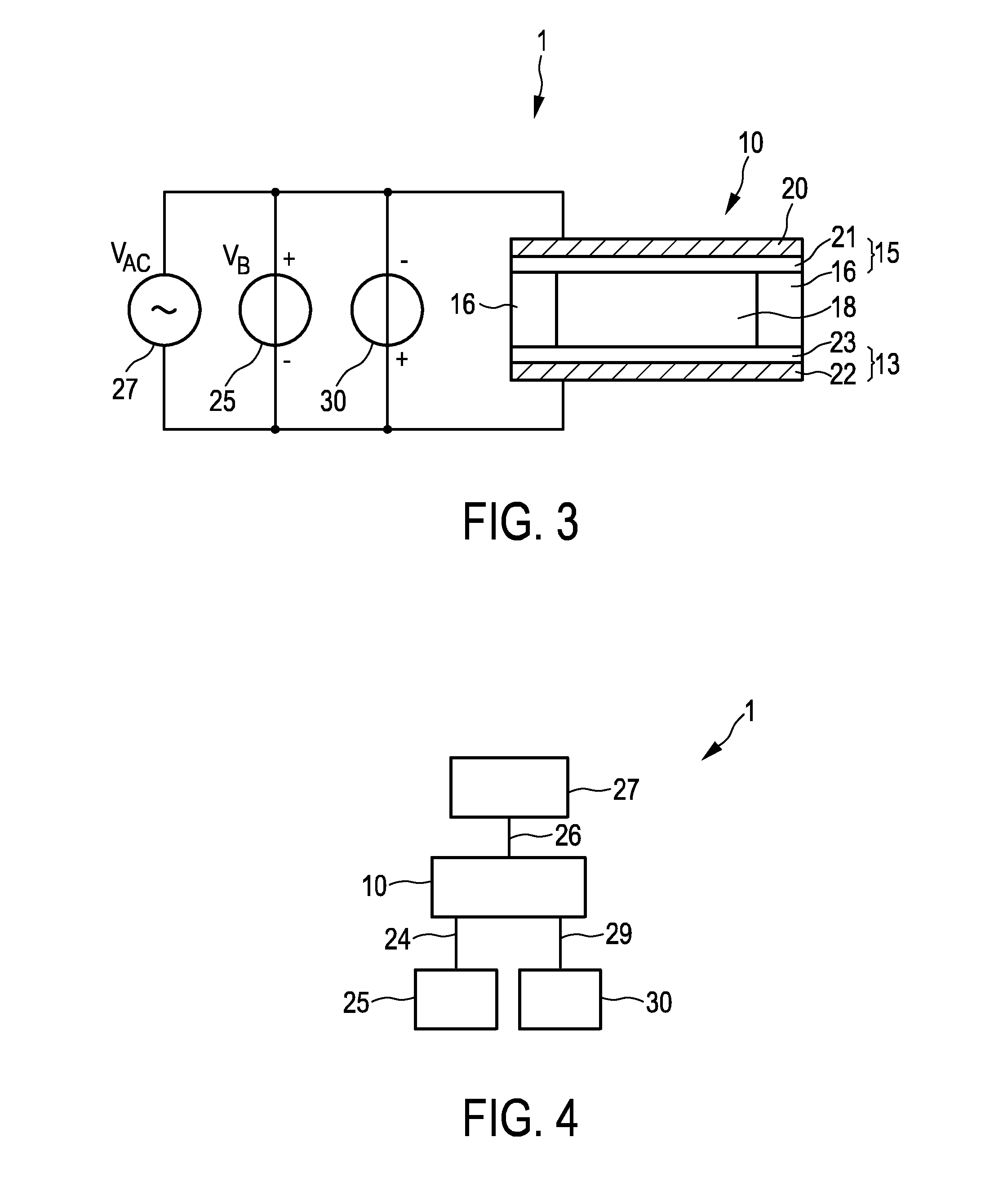
[0037]FIG. 1 shows a schematic cross-sectional view of a typical CMUT cell 10. The CMUT transducer cell 10 is normally fabricated along with a plurality of similar adjacent cells on a substrate 13. The substrate 13 comprises a substrate base layer 12. A diaphragm or membrane 15 is supported above the substrate by an insulating support 16. In this way a cavity 18 is formed between the membrane 15 and the substrate 13. The membrane 15 comprises a membrane base layer 14. The cavity 18 between the membrane and the substrate may be air or gas-filled or wholly or partially evacuated. A conductive film or layer forms a first electrode 22 in the substrate 13, and a similar film or layer forms a second electrode 20 in the membrane 15. These two electrodes 20, 22, separated by the cavity 18, form a capacitance or capacitor. When ultrasound waves in form of an acoustic signal cause the membrane 15 to vibrate the variation in the capacitance can be detected, thereby transducing or transforming ...


PUM

PropertyMeasurementUnit
frequenciesaaaaaaaaaa
operating bias voltageaaaaaaaaaa
charging voltageaaaaaaaaaa

Abstract

The present invention relates to a capacitive micro-machined ultrasound transducer (CMUT) device (1) for transmitting and/or receiving ultrasound waves, comprising at least one CMUT cell (10). The CMUT cell (10) comprises a substrate (13) comprising a first electrode (22), a membrane (15) comprising a second electrode (20), at least one dielectric layer (21, 23) between the first electrode (22) and the second electrode (20), and a cavity (18) formed between the substrate (13) and the membrane (15). The CMUT device (1) further comprises an operating bias voltage source (25) for supplying an operating bias voltage (VB) of a first polarity between the first and second electrode (20, 22) during transmitting and/or receiving ultrasound waves, and a charging voltage source (30) for supplying an additional charging voltage (VC) between the first and second electrode (20, 22), the second polarity being the reverse polarity of the first polarity. The present invention further relates to a method of operating such a CMUT device.

Description

FIELD OF THE INVENTION[0001]The present invention relates to a capacitive micro-machined ultrasound transducer device (CMUT) device for transmitting and / or receiving ultrasound and to a method of operating the same. The present invention can for example be used in a medical ultrasound system (e.g. diagnostic or therapeutic medical ultrasound system), in particular with ultrasound imaging functionality.BACKGROUND OF THE INVENTION[0002]The heart of any ultrasound (imaging) system is the transducer device with its transducer elements or transducer cells which convert electrical energy in acoustic energy and back. Traditionally, these transducer elements or transducer cells are made from piezoelectric crystals arranged in linear (1-D) transducer arrays, and operating at frequencies up to 10 MHz. However, the trend towards matrix (2-D) transducer arrays and the drive towards miniaturization to integrate ultrasound (imaging) functionality into catheters and guide wires has resulted in the...

Claims


Application Information

Patent Timeline
Patent Type & Authority Applications(United States)
IPC IPC(8): B06B1/02G01N29/24
CPCG01N29/2406B06B1/0292
Inventor BROCK-FISHER, GEORGE ANTHONY
Owner KONINKLJIJKE PHILIPS NV
Why Eureka
Try Eureka