Charging electronic cigarette
- Summary
- Abstract
- Description
- Claims
- Application Information
AI Technical Summary
Benefits of technology
Problems solved by technology
Method used
Image

Examples
embodiment 1
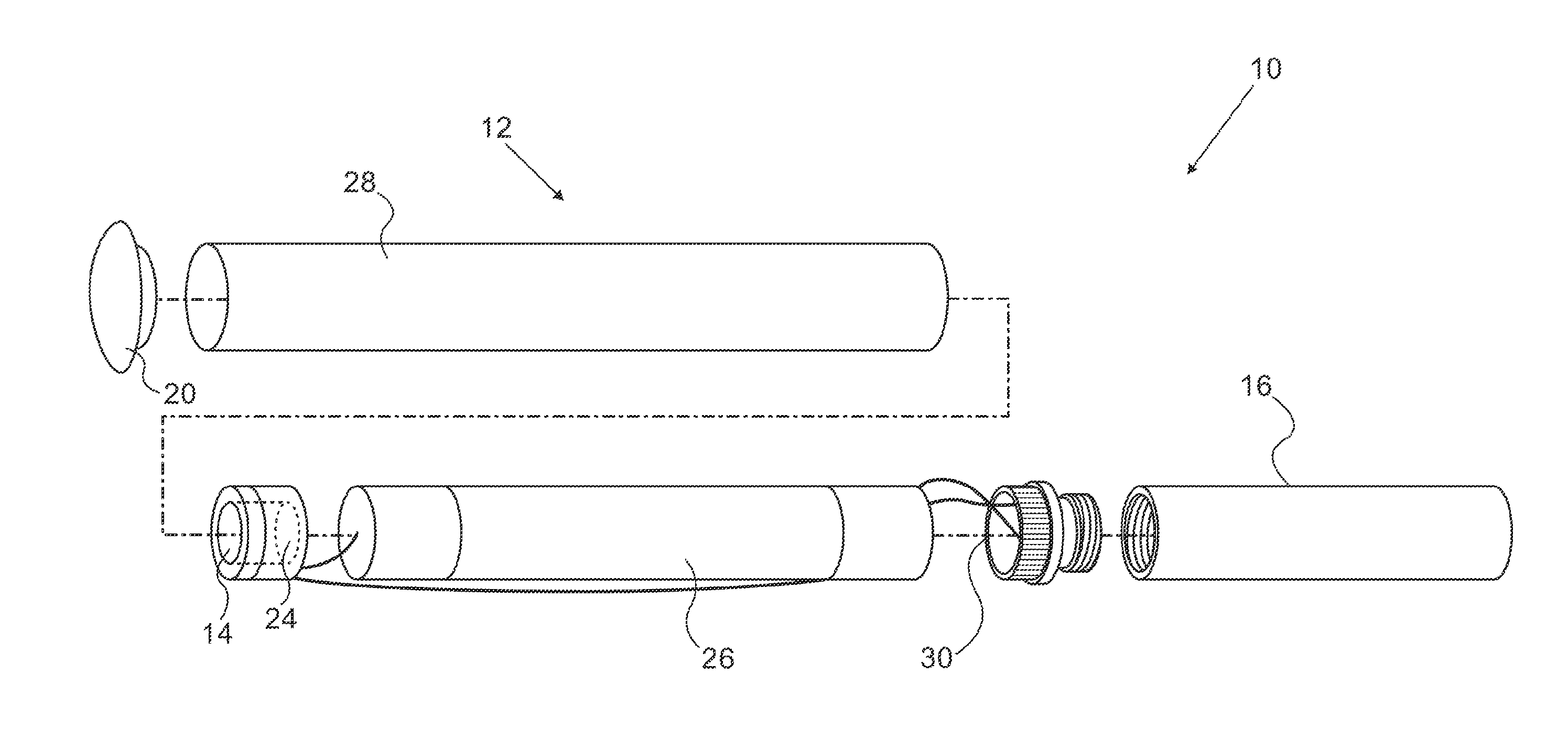
[0058]Turning now to the drawings, reference is initially made to FIG. 1, which is a semi-schematic exploded view of a smoking device 10 in accordance with an embodiment of the invention. Device 10 has a barrel comprising a battery section 12. The battery section 12 may include power control circuitry 14, which is typically encased as a unit with a vacuum sensor 24, and which may be enclosed in a plastic holder. Suitable power controls are disclosed in commonly assigned U.S. Provisional Application No. 61 / 441,133 (WO 2012 / 109371), which is herein incorporated by reference. The device 10 includes a cartridge section 16, including an aerosol generating device having a high resistance electrical wire, which heats a liquid or gel when the aerosol generating device is powered. The liquid is typically a mixture of nicotine, propylene glycol, vegetable glycerine, and flavorings. The components of the section 16 are integral, as taught in commonly assigned U.S. Provisional Application No. 6...
embodiment 2
[0080]Reference is now made to FIG. 14, which is a schematic diagram of electrical circuitry in an electronic cigarette 130 adapted to a battery charger in accordance with an alternate embodiment of the invention. With this embodiment it is possible to connect the external charger while powering the aerosol generating device. The battery charger assembly 96 is now connected to a side port 128 of an electronic cigarette 130 having external contacts 132, 134, which connect in a circuit including the diode 108 and the positive terminal 110 of the battery 104 within battery compartment 105, as in the previous embodiment. When the sensor chip assembly 114 is actuated as the user smokes, it actuates a switch, shown representatively as relay 136, thereby breaking the charger circuit so that the charger is no longer operative. Of course, other types of switches, such as a transistor or field effect transistor could be substituted for relay 136. The sensor chip assembly 114 is typically disp...
embodiment 3
[0097]Reference is now made to FIG. 16, which is a side elevation of a cradle 154 for connection to a battery charging device in accordance with an embodiment of the invention. This version features a circular ring 152 that engages the tip of a cigarette, holding it in contact with the cradle 154. The ring 152 should be made of a rubbery material such as silicone, in order to facilitate holding a cigarette tip inside the cradle 154 by friction. Notches 156 retain magnet 64.
[0098]Reference is now made to FIG. 17, which is a top view of the cradle 154, showing the ring 152, and the magnets 64, 66 in place.
[0099]Reference is now made to FIG. 18, which is a sectional view through the cradle 154, illustrating the magnet 64 being held in place by the notches 156.
PUM
 Abstract
Description
Claims
Application Information
 - Generate Ideas
- Intellectual Property
- Life Sciences
- Materials
- Tech Scout
- Unparalleled Data Quality
- Higher Quality Content
- 60% Fewer Hallucinations
Browse by: Latest US Patents, China's latest patents, Technical Efficacy Thesaurus, Application Domain, Technology Topic, Popular Technical Reports.
© 2025 PatSnap. All rights reserved.Legal|Privacy policy|Modern Slavery Act Transparency Statement|Sitemap|About US| Contact US: help@patsnap.com