Connection structure for superconducting cables

a superconducting cable and connection structure technology, applied in the direction of superconducting magnets/coils, insulated conductors, cables, etc., can solve the problems of increased increased resistance to electrical gradient along the taper surface of the taper shape portion, and reduced resistance to electrical field stress in the stratabound direction. , to achieve the effect of reducing the overall length of the taper portion, suppressing the occurrence of electrical breakdown in the stratabound direction

Active Publication Date: 2015-01-29
FURUKAWA ELECTRIC CO LTD
View PDF0 Cites 3 Cited by
  • Summary
  • Abstract
  • Description
  • Claims
  • Application Information

AI Technical Summary

Benefits of technology

[0023]The present invention forms the taper shape portions in the electric insulating layers at both sides of the conductor connecting part, respectively, and each of the taper shape portions is formed so that its inclination angle changes in a stepwise fashion by including a plurality of tapered portions, among which the tapered portion nearer the conductor connecting part has smaller inclination angle.
[0024]While electrical field stress in the electric insulating layer becomes larger toward the superconductive conductor layer on the inner side, in the tip portion of the taper shape portion, insulation performance is likely to be lowered along the stratabound direction of the taper surface because the superconductive conductor layer on the inner side shrinks by being cooled with the cooling medium. However, according to the present invention, because the inclination angles of each taper shape portion are made so that the inclination angles nearer the front edge (having a smaller diameter) of the taper shape portion are smaller than the inclination angles nearer the posterior edge (having a larger diameter) of the taper shape portion, stratabound-direction components of electrical field stress can be reduced, and thereby occurrence of electrical breakdown in the stratabound direction can be suppressed.
[0025]Moreover, because the taper shape portion has the inclination angles which become larger in a stepwise fashion with increasing distance from the conductor connecting part, the overall length of the taper portion can be reduced in comparison with the case of reducing the inclination angle of the whole taper shape portion, and thereby connection structure can be downsized and the workload necessary for forming it and / or production time can be reduced.
[0026]Furthermore, because in the case of forming the step portion in the taper shape portion, the insulating sheets can be also wound around the outer periphery of the step portion, adhesion becomes high in comparison with the case of winding it around the tapered portion, insulation performance between the taper shape portion and the reinforcing insulating layer can be prevented from being lowered, and thereby it becomes possible to provide the intermediate connection having excellent insulation performance.
[0027]Moreover, because the boundary between the insulating layers is covered with the insulating layer that is further laminated on the insulating layers in the case that the reinforcing insulating layer is composed of the plural layers laminated in order from the inner side, the laminated layers are composed of the wide-width insulating layer and the narrow-width insulating layer, and the wide-width insulating layer is formed so as to cover the entire outer periphery of the narrow-width insulating layer, and thereby the insulation performance at the boundary can be prevented from being lowered and it becomes possible to provide the intermediate connection having excellent insulation performance.

Problems solved by technology

This causes a problem that adhesion between an original insulating portion and a newly formed insulating portion for filling the valley is weakened in each taper shape portion, and thereby resistance to electrical gradient (resistance to electrical field stress) in a stratabound direction along a taper surface of the taper shape portion is decreased.
The resistance to electrical field stress becomes larger toward the inner side, which is near the superconductive conductor, but the adhesion becomes weaker and a gap is more easily formed toward the inner side of the electric insulating portion because the inner side thereof shrinks in not only a longitudinal direction but also a radial direction as the conductor is cooled from an ambient temperature to −200 degrees C., which has been a problem because it further reduces electrical performance of the intermediate connecting part.

Method used


Image

  • Connection structure for superconducting cables
  • Connection structure for superconducting cables
  • Connection structure for superconducting cables

Examples


first embodiment

[0045]Hereinafter, a first embodiment will be described with reference to the drawings.

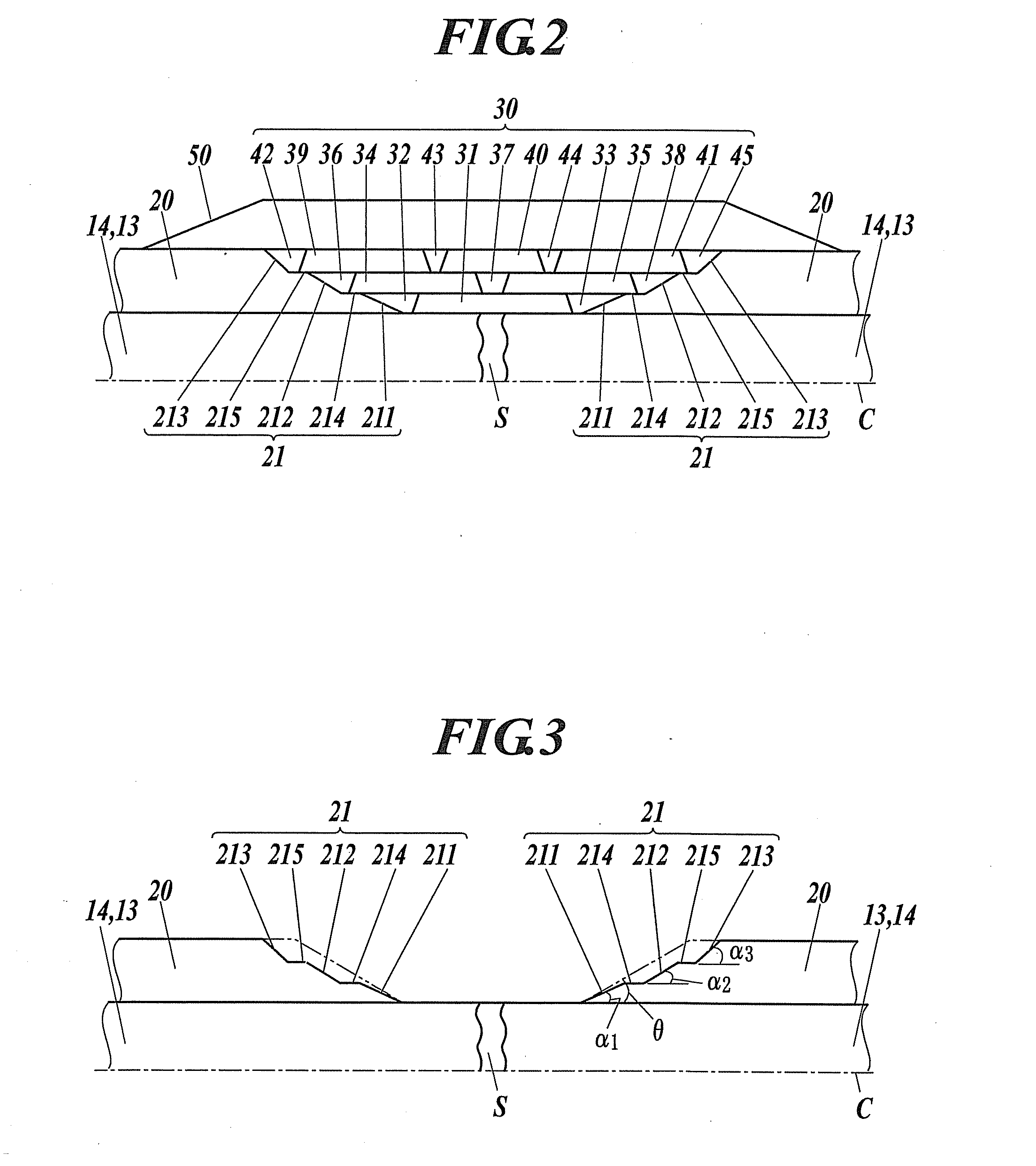
[0046]FIG. 1 is a diagram illustrating an example of superconducting cable to be laid, and FIG. 2 is a cross-sectional view illustrating a major connection structure of a cable core in an intermediate connecting part of the superconducting cable.

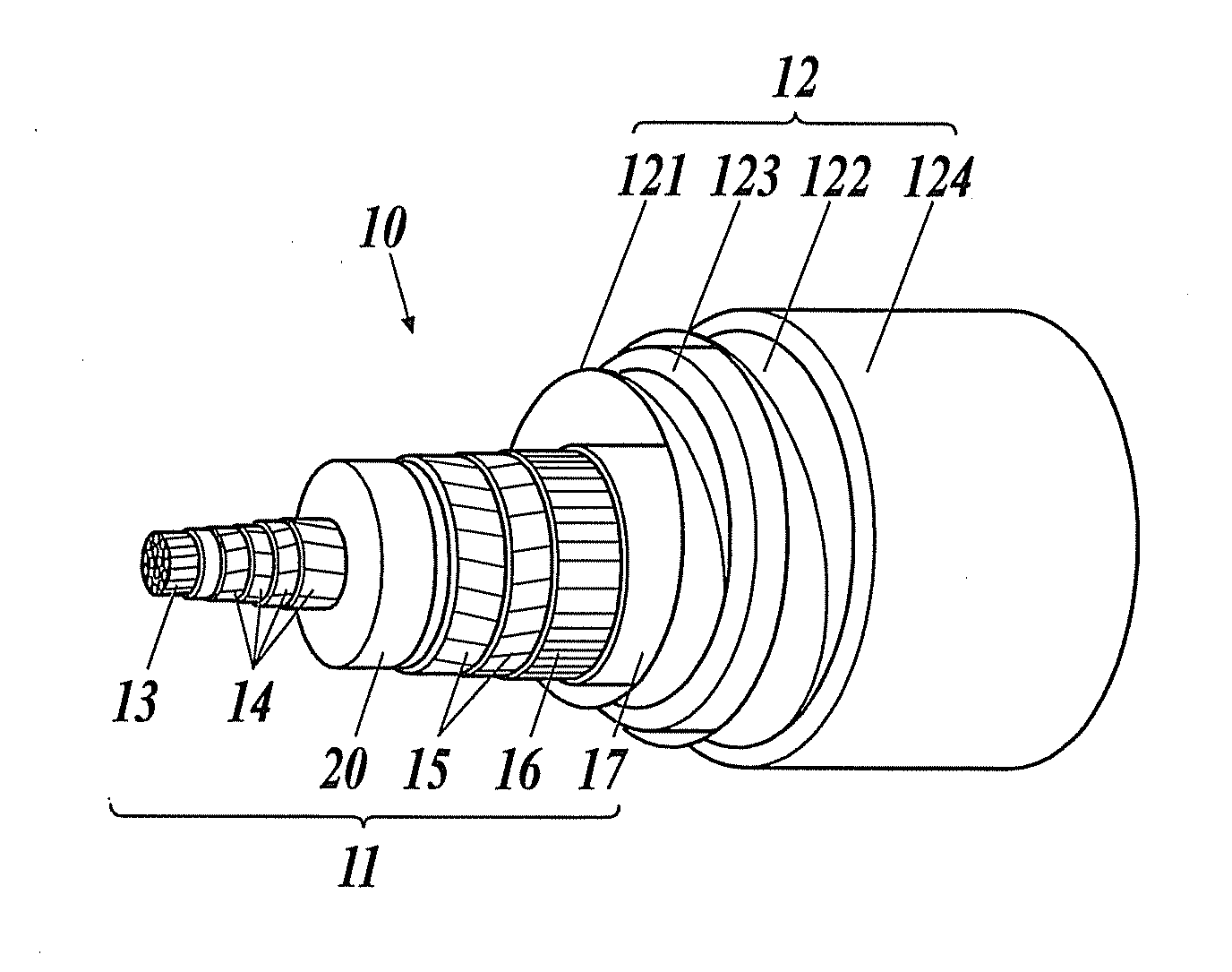
[0047][Superconducting Cable]

[0048]The superconducting cable 10 illustrated in FIG. 1 is a single-core-type superconducting cable in which a single-core cable core 11 is housed in a thermal insulation tube 12. The cable core 11 is composed of a former 13, superconductive conductor layers 14, an electric insulating layer 20, superconducting shield layers 15, a normal conducting shield layer 16, a protecting layer 17, etc.

[0049]The former 13 is a core for winding, which is used to form the cable core 11, and for example, constructed by twisting a normal conducting wire such as a copper wire. Into the former 13, fault current flowing through the superconducti...

second embodiment

[0123]Although the taper shape portion 21 of the first embodiment is composed of three tapered portions 211, 212, 213, it can be composed of a greater number of tapered portions, or composed of a smaller number, two, of tapered portions. In a second embodiment, as illustrated in FIG. 12, the case that each taper shape portion 21A includes the first tapered portion 211, the second tapered portion 212, and the first equal diameter portion 214 will be described. Also in this case, inclination angle α1 of the first tapered portion 211, inclination angle α2 of the second tapered portion 212, and inclination angle θ of a conventional taper shape portion including a single tapered surface are set so that α12, α12>θ. Specifically, they are set so that α1=2.3, α2=4.2 (θ=3.45 degrees).

[0124]Moreover, in the case that the equal diameter portion 214 is not considered, in x-y coordinate system in which the direction along the cable centerline C is defined as x and the cable radial direction cent...

third embodiment

[0135]In a third embodiment, as illustrated in FIG. 15, the taper shape portion 21B has the feature of being composed of a plurality (for example, n) of the first to nth stepwise tapered portions 211B, 212B, 213B, . . . , and having inclination angles α1 to αn of the first to nth tapered portions 211B, 212B, 213B, . . . set so as to fulfill following condition formulas (7) to (12).

[0136]Incidentally, though the case that no equal diameter portion (no step portion) is provided at boundaries between the tapered portions is illustrated in the example of FIG. 15, it is also possible to provide the equal diameter portions (step portions). Additionally, in the case of providing the equal diameter portions (step portions), the overall length of the equal diameter portions (step portions) is added to each value of X2 to Xn.

[Formula7][FIRSTSTEP]A·sinα1y<1(r≦y<Y1),y=r+x·tanα1(0≦x<X1)(7)[SECONDSTEP]A·sinα2y<1(Y1≦y<Y2),y=r+X1tanα1+(x-X1)tanα2(X1≦x<X2)(8)[THIRDSTEP]A·sinα3y<...


PUM

PropertyMeasurementUnit
lengthaaaaaaaaaa
lengthaaaaaaaaaa
widthaaaaaaaaaa

Abstract

A connection structure for superconducting cables includes: superconducting cables that are connected to each other and include cable cores containing formers and superconducting conductor layers, and each cable core is housed in a thermal insulation tube with a cooling medium, wherein the cable cores include electric insulating layers obtained by winding insulating sheets around the superconducting conductor layers, the electric insulating layers on both sides of a conductor connecting part, in which the formers and the superconducting conductor layers are connected to each other, include taper shape portions each having a diameter reducing towards the conductor connecting part, each taper shape portion is formed so as to have an inclination angle changing in a stepwise fashion by a plurality of tapered portions among which a tapered portion nearer the conductor connecting part has smaller inclination angle, and a reinforcing insulating layer is provided between the taper shape portions.

Description

TECHNICAL FIELD[0001]The present invention relates to a connection structure for superconducting cables for transmitting electrical power.BACKGROUND ART[0002]Heretofore, there is known a superconducting cable using superconducting wire material as a conductor, which material becomes a superconducting state at an ultralow temperature. The superconducting cable is expected to serve as a power cable capable of transmitting large current with low loss, and is being developed for practical use.[0003]The superconducting cable has a structure in which a cable core is housed in a thermal insulation tube, and the cable core is constructed by laminating a former, a superconductive conductor layer, an electric insulating layer, etc. in order from the center of the cable core.[0004]The thermal insulation tube has a double tube structure having an internal tube and an external tube, wherein vacuum evacuation is performed between the internal tube and the external tube, and a cooling medium such ...

Claims


Application Information

Patent Timeline
Patent Type & Authority Applications(United States)
IPC IPC(8): H01B12/02H01B7/02
CPCH01B7/0241H01B12/02H01R4/68H02G15/34Y02E40/60H10N60/80
Inventor YAGI, MASASHINOMURA, TOMOYAHIRATA, HIRAOMITSUHASHI, TAKAHARU
Owner FURUKAWA ELECTRIC CO LTD
Why Eureka
Try Eureka