Wireless power control system

a power control system and wireless technology, applied in the direction of electrial characteristics varying frequency control, safety/protection circuit, battery overheat protection, etc., can solve the problems of reducing the overall efficiency of the system, generating significant heating, and reducing the efficiency so as to reduce the q factor reduce the resonator circuit effect, and eliminate the effect of the resonator circui

Active Publication Date: 2015-02-05
BEIJING XIAOMI MOBILE SOFTWARE CO LTD
View PDF7 Cites 39 Cited by
  • Summary
  • Abstract
  • Description
  • Claims
  • Application Information

AI Technical Summary

Benefits of technology

[0013]In one embodiment, the resonator circuit can include a resonator shut off circuit. The resonator shut off circuit can be the control subcircuit or a switch that is separate from the control subcircuit. The resonator circuit or control subcircuit can include a sensor for providing information relevant to the control of the shut off circuit. For example, the resonator shut off circuit can be used to effectively eliminate the resonator circuit from the wireless receiver.
[0014]In one embodiment, the present invention can be incorporated into a wireless transmitter with a primary inductor that relays power through a primary resonator circuit. The wireless transmitter includes a control subcircuit to adjust the Q factor of the primary resonator circuit to regulate the amount of power emanating from the wireless transmitter. In one embodiment, the wireless transmitter includes a controller that operates the control subcircuit based on any desired control characteristic. For example, the wireless transmitter may limit the amount of power transmitted to correspond with the amount of power desired by the wireless receivers.
[0015]In one embodiment, the wireless transmitter is configured to operate in conjunction with wireless receivers with Q control. The wireless receivers may be configured to communicate their Q control status to the wireless transmitter. The wireless transmitter may be configured to reduce the Q factor of the resonator circuit when all of the wireless receivers are using Q control.
[0016]The present invention may provide a variety of benefits. In one embodiment, the present invention simple resonant feedback and Q control for a highly resonant system. The present invention may provide simple control for allowing one field transmitter to power many receivers, including receivers at different power levels. The present invention allows the control system to control Q at the transmitter and / or receiver, or in intermediate components. The present invention allows a transmitter with Q control to limit power or control Q allowing multiple proximity systems, such as close coupling and mid-range systems. In one embodiment, the present invention provides a simple battery charger and feedback system that can be incorporated into a label of a battery. The present invention may allow a system to control Q along with communicating the receiver's power needs while using rail voltage, phase control, or frequency to adjust for maximum efficiency. The present invention may allow analog Q control with digital monitoring and communications. In one embodiment, the present invention may be incorporated into a control system that allows fixed frequency, variable frequency, variable rail (amplitude), variable range (distance) and multiple power transfer protocols. The present invention allows control for switching between highly resonant systems loosely coupled and tightly coupled inductive systems. The present invention may incorporate a transmitter that can control power to many receivers at various distances, adjusting to the maximum distance with required power while the other receivers reduce Q to adjust power as needed. The present invention may allow Q control based on a variety of factors, such as voltage, current or temperature.

Problems solved by technology

Although the use of resonators typically provides improved efficiency in mid-range environments, resonators can reduce efficiency when the wireless power supply and the remote device are too close.
This can lead to reduce the system's overall efficiency, generate significant heating and produce excessive voltages and circulating currents at the receiver.

Method used


Image

  • Wireless power control system
  • Wireless power control system
  • Wireless power control system

Examples


Embodiment Construction

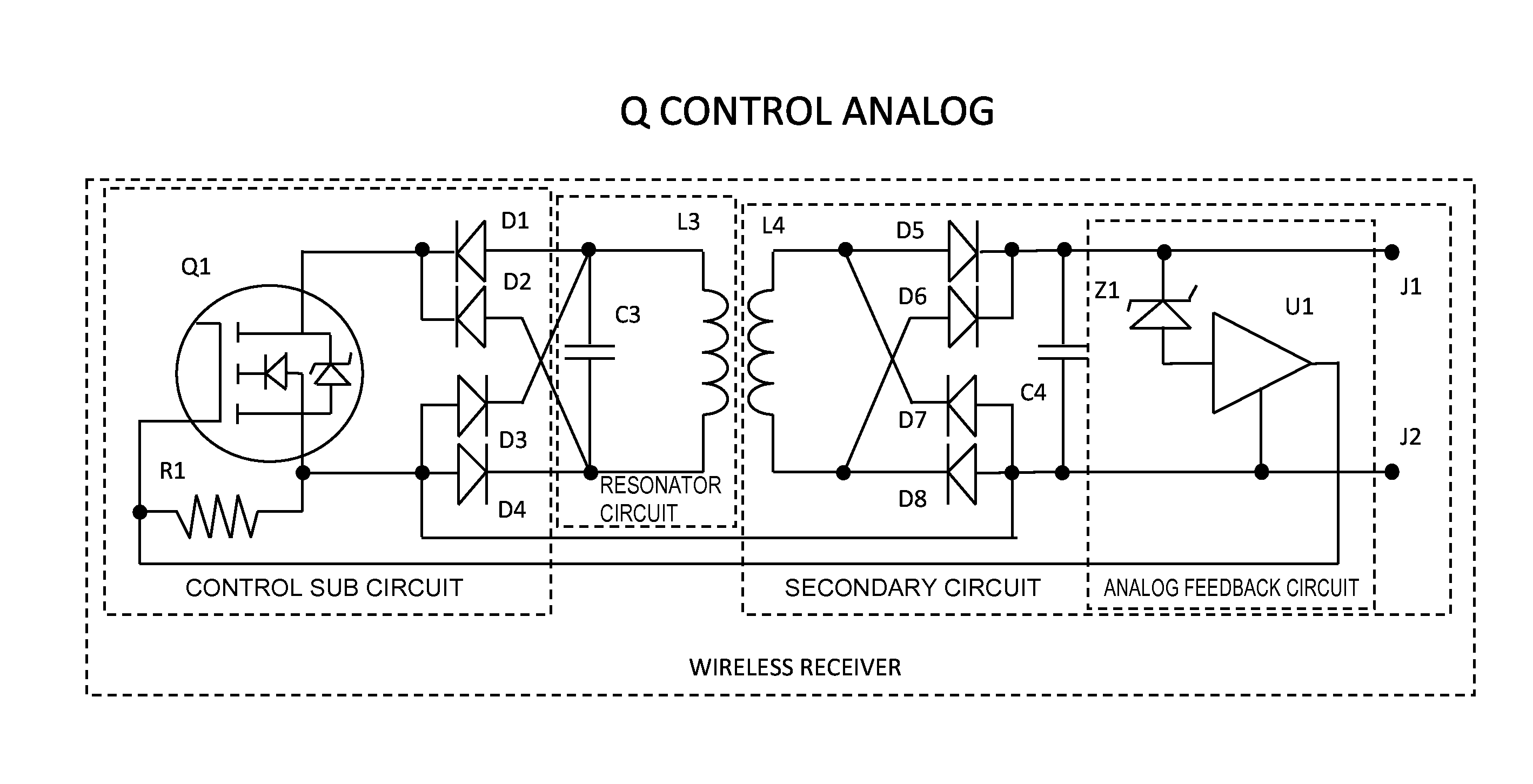
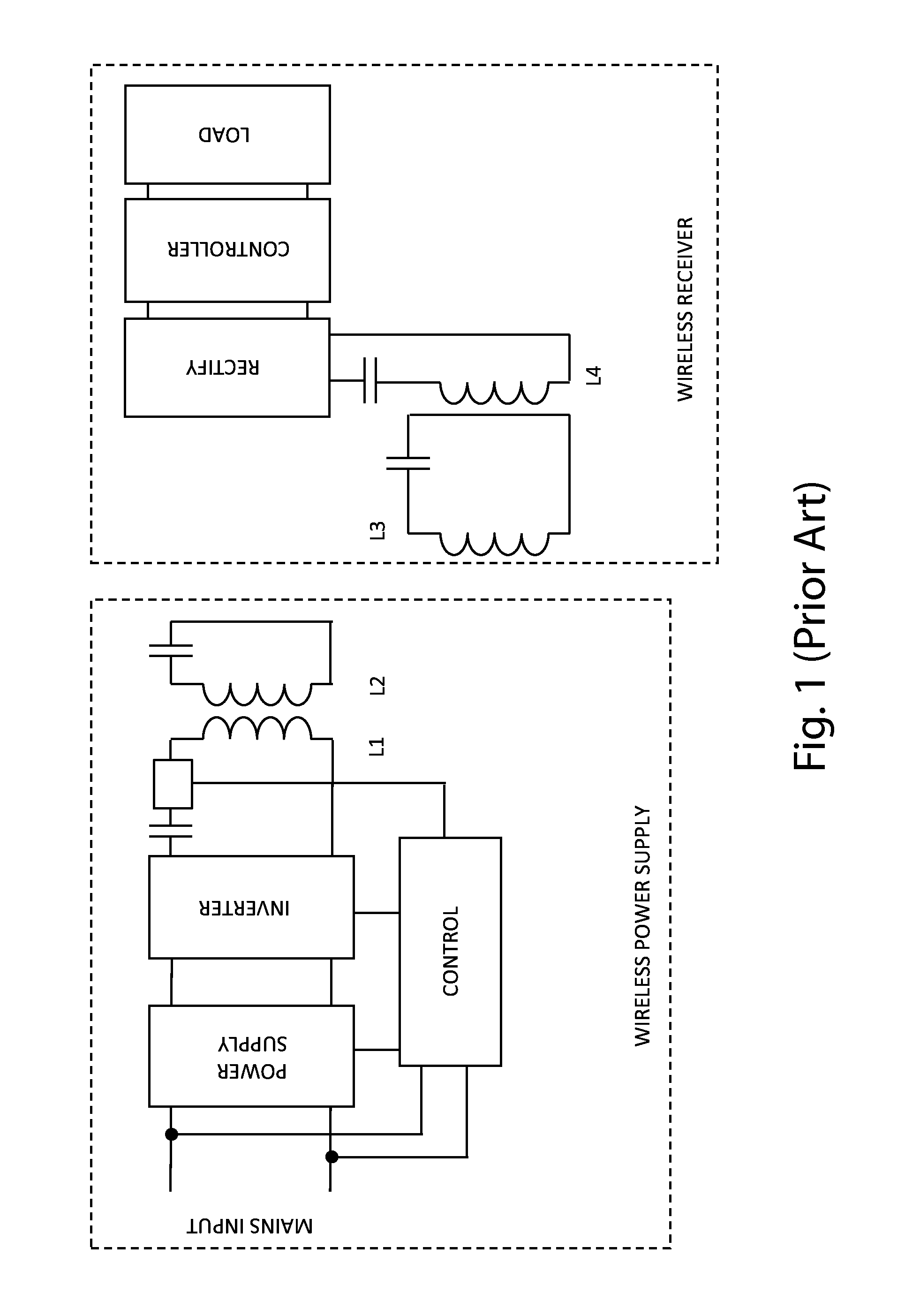
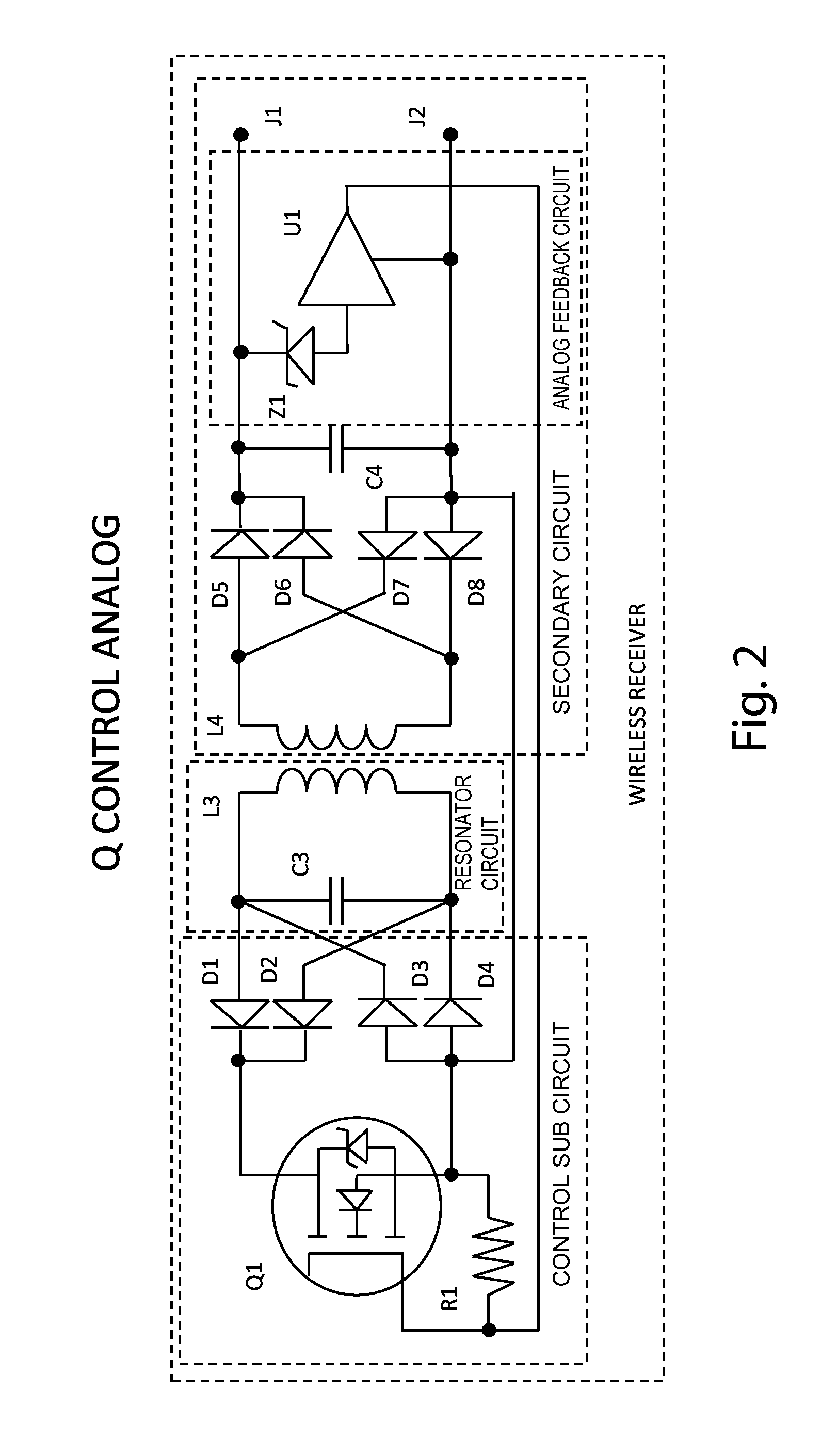
[0056]Conventional mid-range wireless power systems may include resonators that relay power from the wireless power transmitter to the wireless power receiver. In general, the higher the Q factor of the resonators, the lower the rate of energy loss relative to the stored energy of the resonator. That is, the higher the Q factor, the slower the oscillations in the resonator die out. As a result, the Q factor of a resonator is relevant to the amount of power that can be relayed by the resonator at a given distance. A higher Q factor can result in higher power relay and a lower Q factor can reduce the amount of power relayed. Actively configuring one or more of the resonators to control the Q factor of the resonator circuit can allow regulation of the amount of power passing through the wireless power transfer system, such as by regulating the amount of power emanating from the wireless power supply or the amount of power received in the remote device. A wireless receiver in accordance...


PUM

PropertyMeasurementUnit
frequencyaaaaaaaaaa
output voltageaaaaaaaaaa
threshold voltageaaaaaaaaaa

Abstract

A wireless power transfer component with a selectively adjustable resonator circuit having a Q control subcircuit that varies the Q factor of the resonator circuit to control the amount of power relayed by the resonator circuit. The resonator circuit may be in the wireless power supply, the wireless power receiver, an intermediate resonator or any combination thereof. The resonator circuit may be actively configured based on a feedback circuit. The feedback circuit may sense a characteristic in the secondary circuit or elsewhere and actively operate the control subcircuit based on the sensed characteristic. The feedback circuit may cause the Q control subcircuit to change (reduce or increase) the Q factor when the sensed characteristic crosses a threshold value. The Q control subcircuit may include a variable resistor having a value that can be varied to adjust the Q factor of the resonator circuit.

Description

BACKGROUND OF THE INVENTION[0001]The present invention relates to wireless power transfer.[0002]The use of wireless power supply systems continues to grow. The most common wireless power supply systems use electromagnetic fields to wirelessly transfer power from a wireless power supply to wireless power receiver associated with a remote device, such as a cell phone, a smart phone, a media player or other electronic device. There are a number of different types of wireless power supply systems. For example, many conventional systems use a primary coil in the wireless power supply and secondary coil in the wireless power receiver of the remote device. The primary coil generates an electromagnetic field that emanates from the wireless power supply. The wireless power receiver includes a secondary coil that can be placed within the electromagnetic field generated by the primary coil. When the remote device is placed within sufficient proximity to the wireless power supply, the electroma...

Claims


Application Information

Patent Timeline
Patent Type & Authority Applications(United States)
IPC IPC(8): H03J7/04H02J7/02H01F38/14H02J5/00H04B5/00
CPCH03J7/04H02J5/005H02J7/025H01F38/14H04B5/0037H02J7/00309H02J7/00308Y02T10/70H02J50/80H02J50/12H02J50/40Y02T10/7072Y02T90/14H02J7/0045B60L53/12
Inventor BAARMAN, DAVID W.MOES, BENJAMIN C.SCHWANNECKE, JOSHUA K.TAYLOR, JOSHUA B.KUYVENHOVEN, NEIL W.NORCONK, MATTHEW J.MOORE, COLIN J.LORD, JOHN JAMESBLOOD, KRISTEN J.
Owner BEIJING XIAOMI MOBILE SOFTWARE CO LTD
Why Eureka
Try Eureka