Look-up table architecture

a look-up table and look-up table technology, applied in the field of look-up table architecture, can solve the problems of high investment, inability to realize the structure with small registers, and inability to change the morphology and functionality of asics, so as to achieve fast operation, improve manufacturing yield, and reduce costs

Active Publication Date: 2015-02-05
S O I TEC SILICON ON INSULATOR THECHNOLOGIES
View PDF6 Cites 2 Cited by
  • Summary
  • Abstract
  • Description
  • Claims
  • Application Information

AI Technical Summary

Benefits of technology

[0069]As a result of such approach, a compact FPGA can be realized. Furthermore, due to the dense layout, the costs can be reduced. Additionally, with the driving of the output signal b...

Problems solved by technology

However, the realization of an ASIC requires a high level of investments, since an entire set of lithographic masks has to be developed.
Additionally, once finalized, the ASIC morphology and functionality cannot be changed.
In turn, this implies that such a structure cannot be realized with small registers since they would lack the appropriate current driving capabilities.
In particular, small SRAM, small DRAM and registers realized using flash technology are generally not powerful enough for such constructions.
This increases the propagation delay and, therefore, the operating frequency of the circuit.
This translates in delay to establish the signal and/or sensitivity to the noise.
However, this further increases...

Method used


Image

  • Look-up table architecture
  • Look-up table architecture
  • Look-up table architecture

Examples


Embodiment Construction

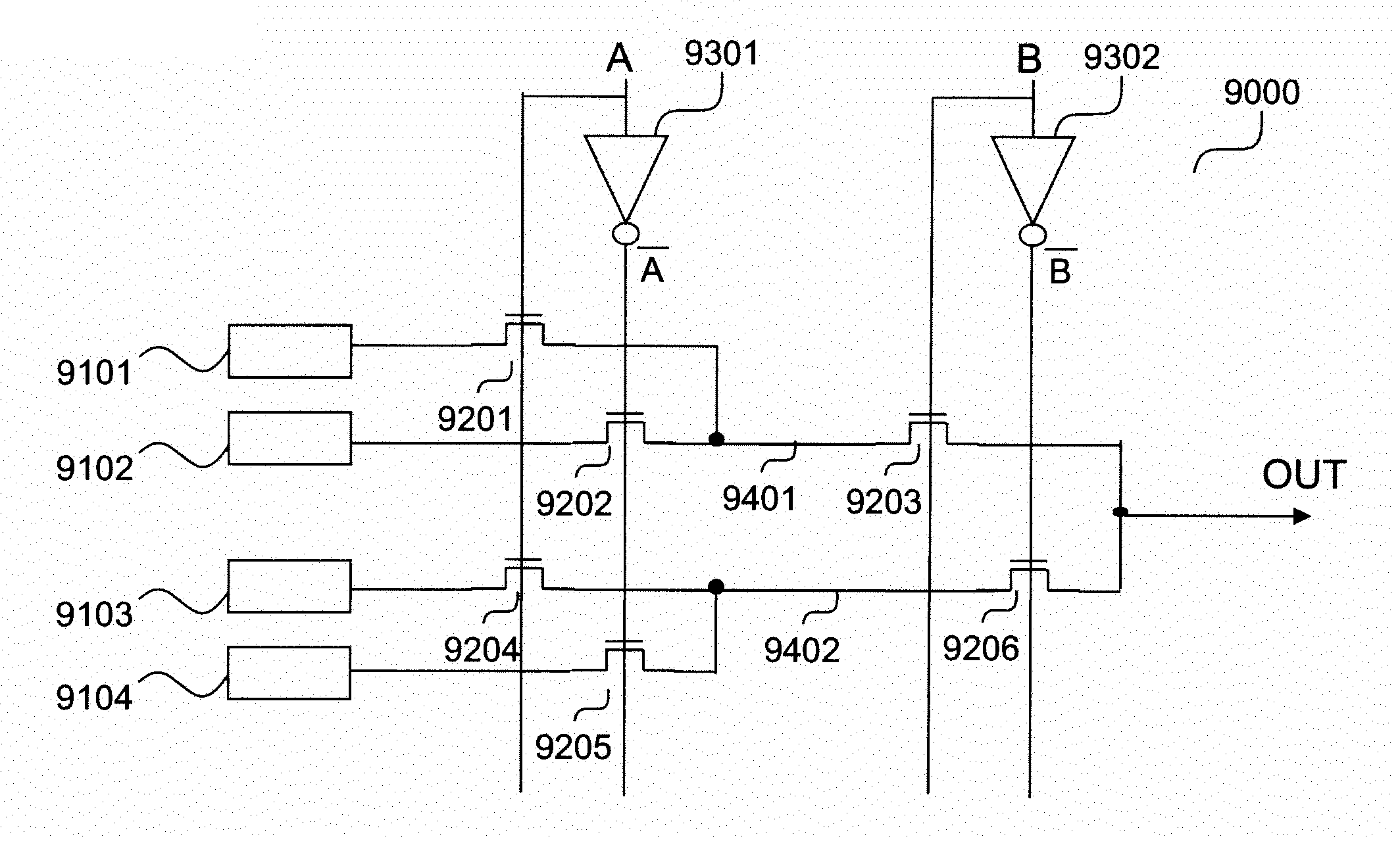
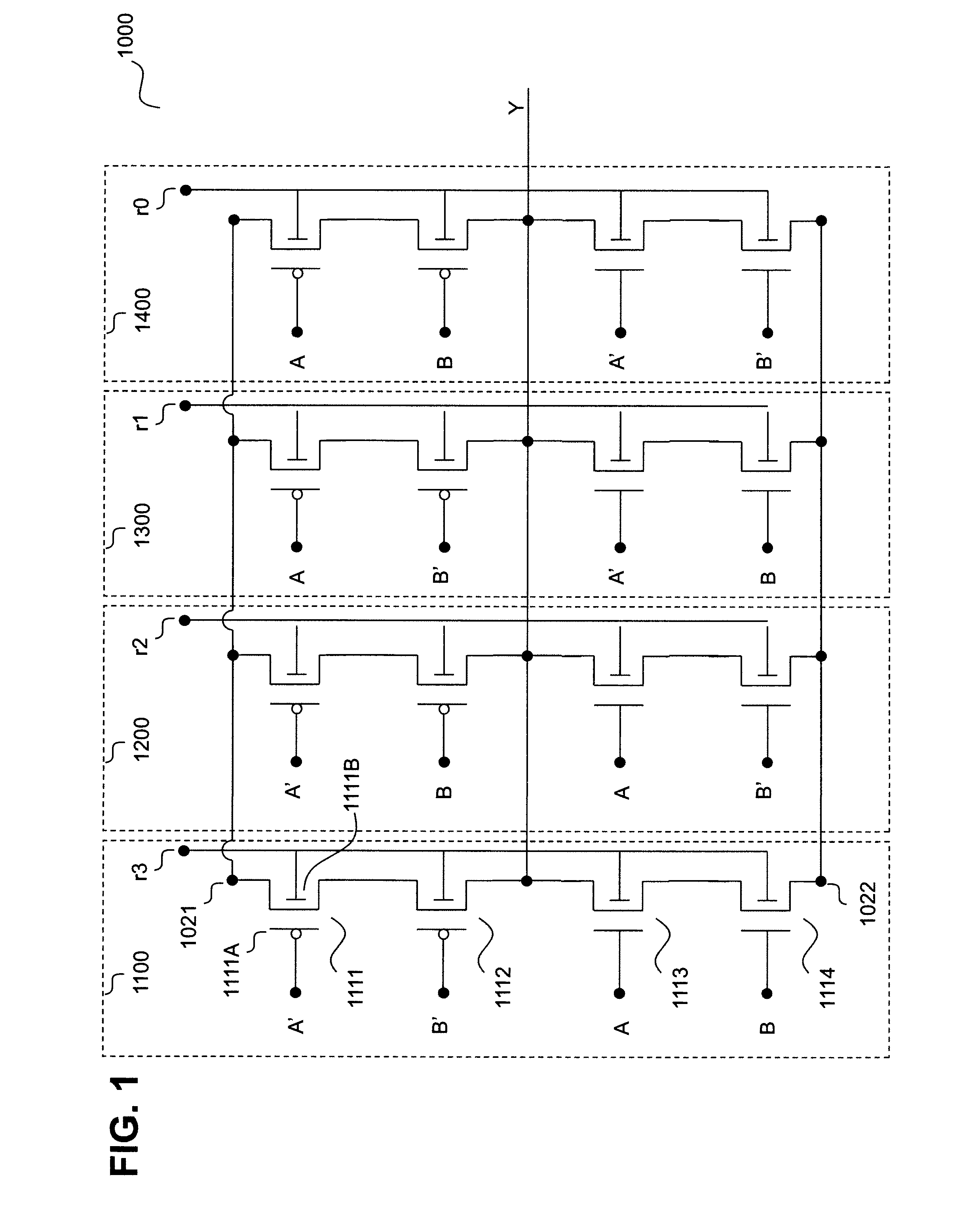
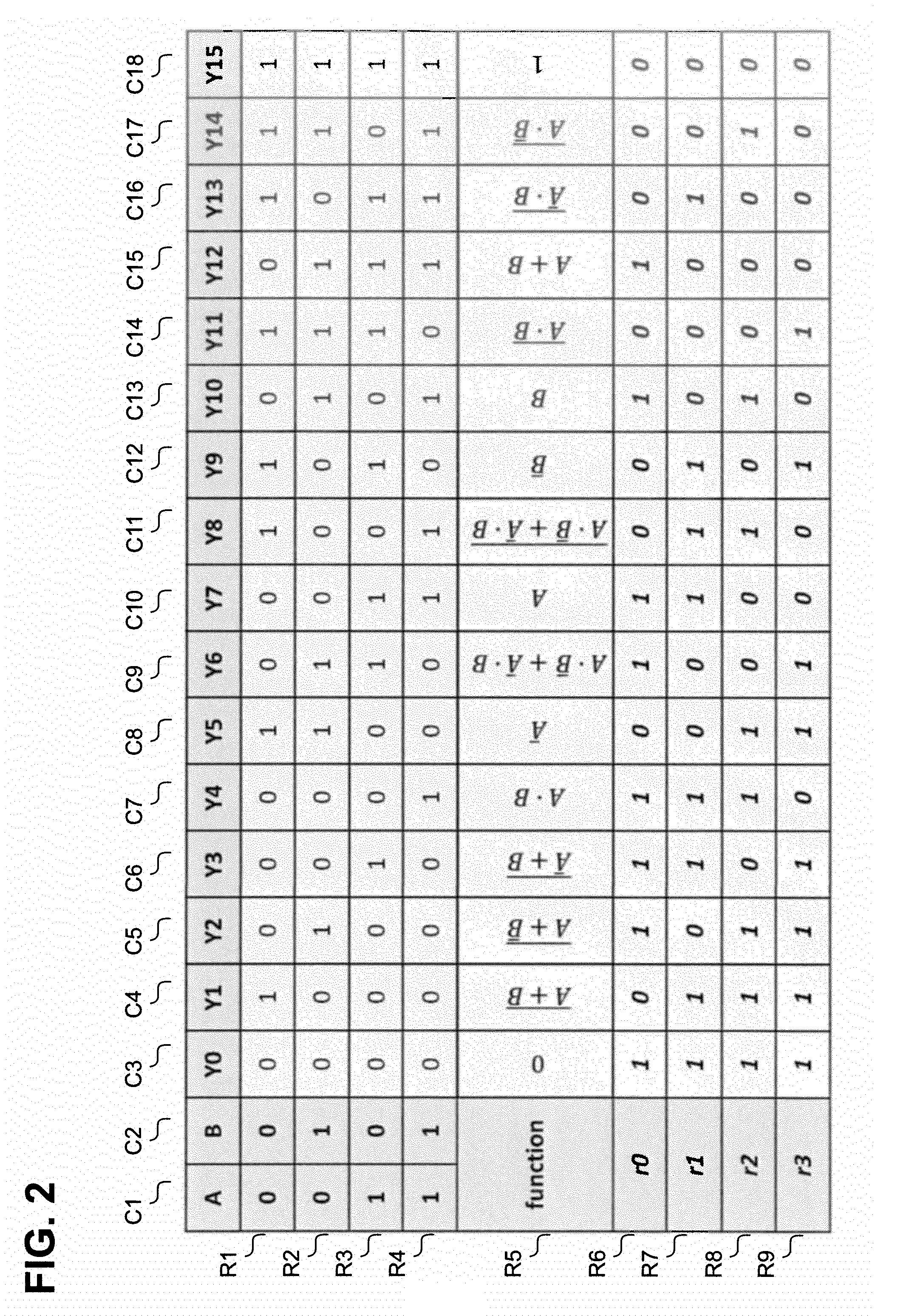
[0083]As can be seen in FIG. 1, illustrating a schematic view of a look-up table 1000 in accordance with an embodiment of the present invention, look-up table 1000 receives two input signals A and B and their respectively negated versions A′ and B′, as well as a plurality of register signals r0-r3. Based on the values assigned to the plurality of register signals r0-r3, the look-up table 1000 allows the realization of any Boolean function of the input signals A and B, as will be described below.

[0084]Although not illustrated in the figure, it will be clear to those skilled in the art that input signals A, A′, B and B′ could be inputted, or that any of input signals A and B could be inputted and its negated version obtained by means of an inverter.

[0085]Additionally, although not illustrated in the figure, register signals may be provided by a plurality of registers that may be comprised within the look-up table 9000.

[0086]Additionally, look-up table 1000 provides an output signal Y....


PUM


Abstract

The present invention relates to a look-up table architecture and to an FPGA comprising the same. The look-up table architecture comprises a registers group comprising a plurality of registers configured to issue register signals, and a programmable logic comprising a plurality of pass gates configured to be controlled at least by the register signals, the registers group and the programmable logic forming a look-up table, wherein the pass gates are placed in a single direction.

Description

CROSS-REFERENCE TO RELATED APPLICATIONS[0001]This application is a national phase entry under 35 U.S.C. §371 of International Patent Application PCT / EP2013 / 053568, filed Feb. 22, 2013, designating the United States of America and published in English as International Patent Publication WO 2013 / 131765 A1 on Sep. 12, 2013, which claims the benefit under Article 8 of the Patent Cooperation Treaty and under 35 U.S.C. §119(e) to French Patent Application Serial No. 1252003, filed Mar. 5, 2012, the disclosure of each of which is hereby incorporated herein in its entirety by this reference.TECHNICAL FIELD[0002]The present invention relates to the field of electronics, in particular, to the field of semiconductors.BACKGROUND[0003]For implementing functions within a semiconductor circuit, it is customary to use a multitude of standard cells in what is called an Application Specific Integrated Circuit (ASIC). This approach has the advantage of providing a compact solution, together with a fas...

Claims


Application Information

Patent Timeline
IPC IPC(8): H03K19/177H03K19/003H03K19/00
CPCH03K19/17728H03K19/17792H03K19/00315H03K19/0013H01L2924/0002
Inventor FERRANT, RICHARD
Owner S O I TEC SILICON ON INSULATOR THECHNOLOGIES
Why Eureka
Try Eureka