
Display Device Using a Demultiplexer Circuit

a demultiplexer and display device technology, applied in the field of active matrix display, can solve the problems of longitudinal dim that is very noticeable, reduce image quality, and high cost of data driving circuit, and achieve the effect of preventing current deviation

Active Publication Date: 2015-02-05
LG DISPLAY CO LTD
View PDF4 Cites 29 Cited by
  • Summary
  • Abstract
  • Description
  • Claims
  • Application Information

AI Technical Summary

Benefits of technology

The invention aims to design a circuit and control signals that prevent current deviation between pixels of the same color in an organic light emitting display. This is achieved by ensuring that the kickback voltage influences each pixel the same number of times.

Problems solved by technology

This results in a higher cost of the data driving circuit.
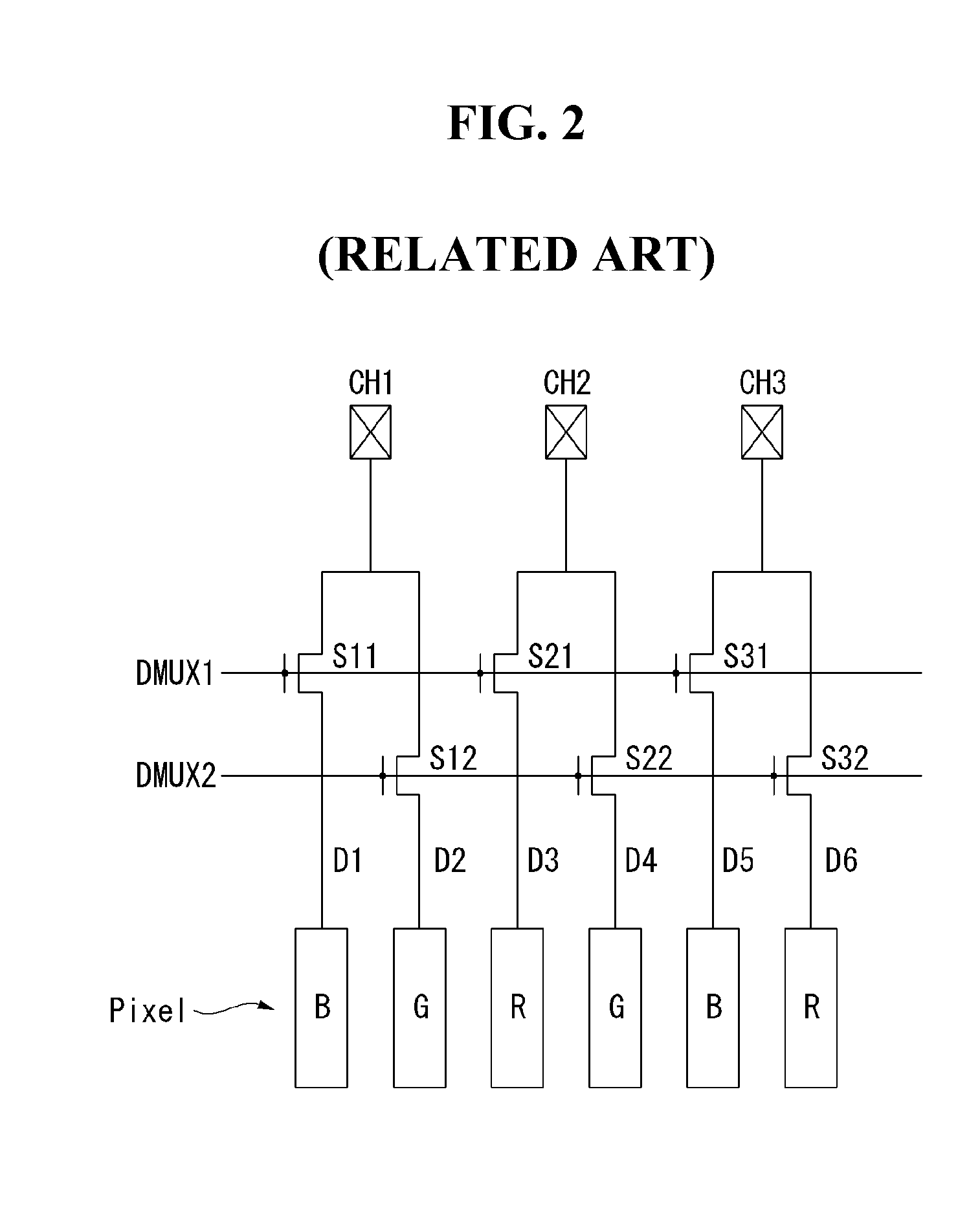
The current deviation generates a longitudinal dim and thus reduces image quality.
However, when the pixels generating the unwanted current deviation display the same color, the unwanted current deviation results in a longitudinal dim that is very noticeable.

Method used


Image

  • Display Device Using a Demultiplexer Circuit
  • Display Device Using a Demultiplexer Circuit
  • Display Device Using a Demultiplexer Circuit

Examples


first embodiment

[0057]An organic light emitting display according to a first embodiment of the invention includes a demux switching circuit for a 1 to N demux, so that pixels displaying the same color are influenced the same number of times by a kickback voltage in a demux driving method. Further, the organic light emitting display according to the first embodiment of the invention generates the first to Nth demux control signals, which sequentially rise to an on-level and then sequentially fall to an off-level in a programming period, in which a first scan signal is held at an on-level so as to apply data voltage Vdata to pixels.

[0058]FIG. 6 shows an example of the demux switching circuit for 1 to 2 demux in the organic light emitting display according to the first embodiment of the invention. FIG. 7 shows driving timing of the pixel shown in FIG. 5 and the demux switching circuit shown in FIG. 6. FIGS. 8A to 8D show an operation state of a pixel in each of driving stages.

[0059]The demux switching...

second embodiment

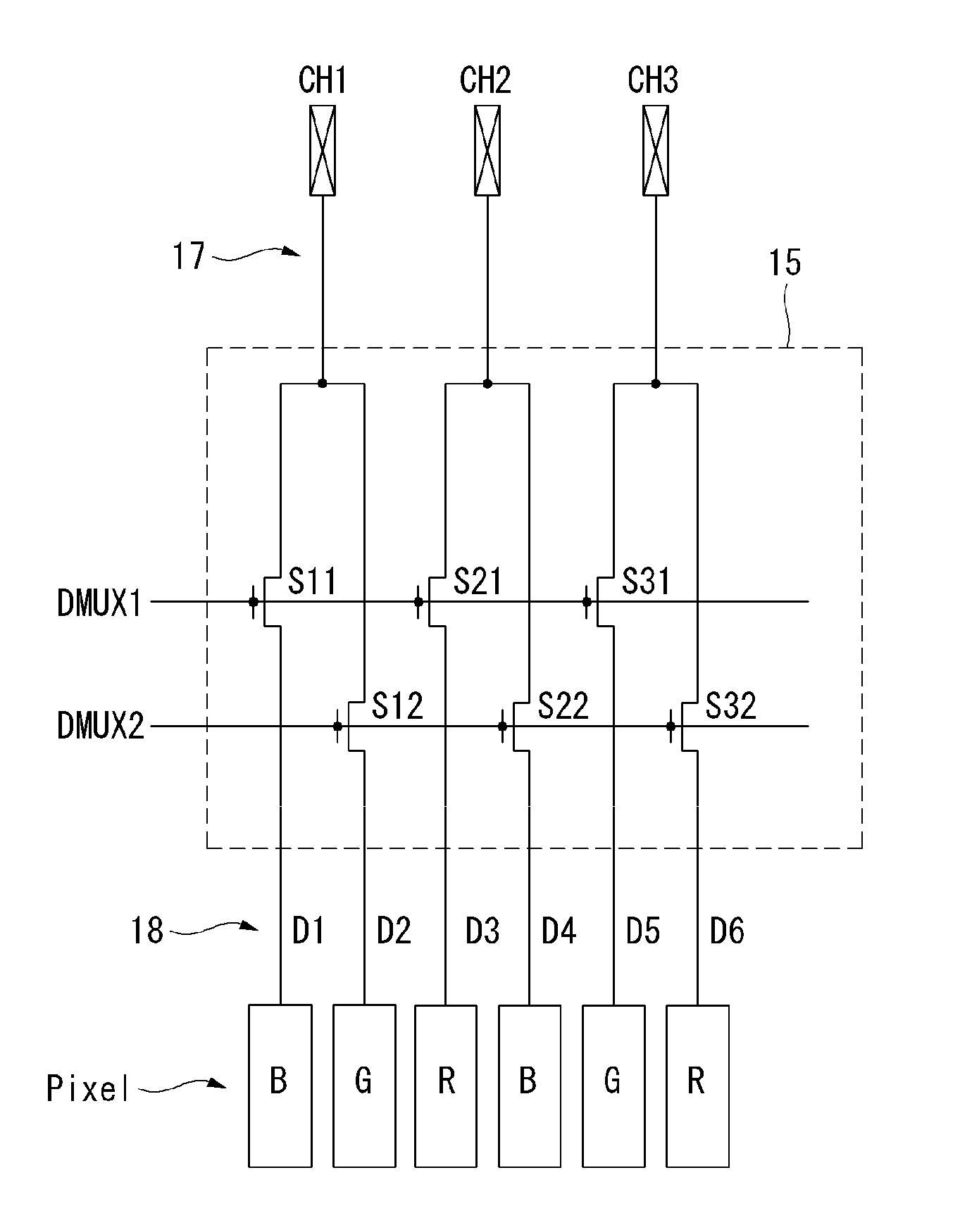
[0084]An organic light emitting display according to a second embodiment of the invention includes a demux switching circuit which includes first and second demux switches connected to some of the output channels of a data driving circuit and time-division supplies a data voltage received from these output channels of the data driving circuit to two data lines of a display panel, so that pixels displaying the same color are influenced by a kickback voltage the same number of times in a demux driving method.

[0085]FIG. 15 shows an example of the demux switching circuit for a 2 to 3 demux in the organic light emitting display according to the second embodiment of the invention. FIG. 16 shows driving timing of the pixel shown in FIG. 5 and the demux switching circuit shown in FIG. 15.

[0086]The demux switching circuit 15 shown in FIG. 15 includes first demux switches S11 and S31, and second demux switches S12 and S32, which are connected to output channels CH1 and CH3 of the data driving...


PUM


Abstract

A display device is disclosed to include a display panel including a plurality of data lines, a plurality of gate lines, and a plurality of pixels coupled to the data lines and gate lines. The data lines include first and second data lines, and the pixels include first and second color pixels. The display device also includes a data driving circuit to generate data voltages through a plurality of output channels, a gate driving circuit coupled to the gate lines, and a timing controller to generate control signals to the data driving circuit and the gate driving circuit. The display device further includes a demultiplexer switching circuit with first demux switches to supply, when turned on, the data voltages from the output channels to the first data lines, and second demux switches to supply, when turned on, the data voltages from the output channels to the second data lines.

Description

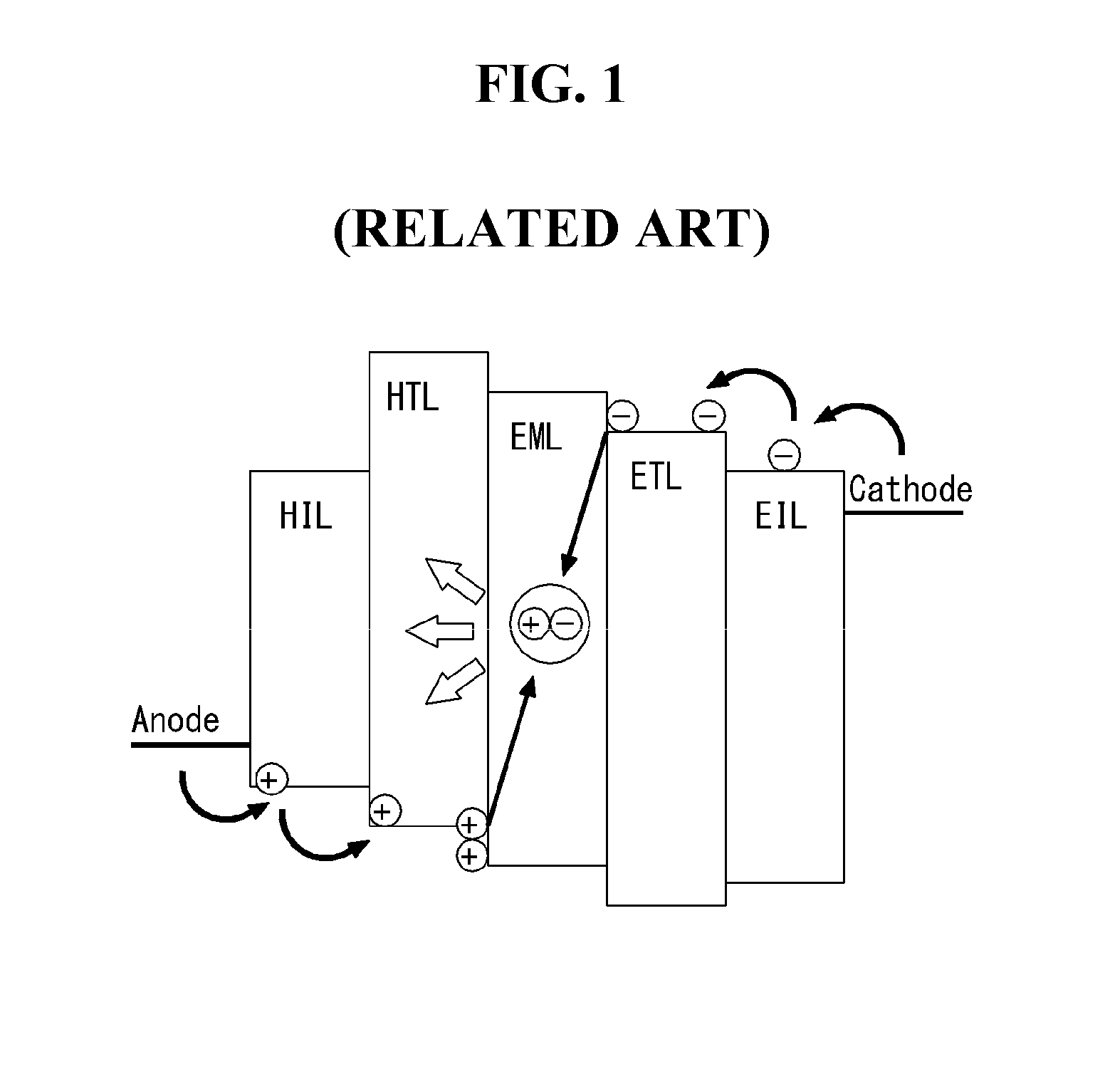
[0001]This application claims the benefit of Korea Patent Application No. 10-2013-0091060 filed in Korea on Jul. 31, 2013, the entire contents of which is incorporated herein by reference for all purposes as if fully set forth herein.BACKGROUND OF THE INVENTION[0002]1. Field of the Invention[0003]The present invention relates to an active matrix display and, more particularly, to an active matrix organic light emitting display utilizing a demultiplexer to supply data voltages from data drivers to pixels.[0004]2. Discussion of the Related Art[0005]An active matrix organic light emitting display includes organic light emitting diodes (hereinafter, abbreviated to “OLEDs”) capable of emitting light by itself, and has advantages, such as fast response time, high light emitting efficiency, high luminance, and wide viewing angle.[0006]The OLED serving as a self-emitting element has a structure shown in FIG. 1. The OLED includes an anode electrode, a cathode electrode, and an organic compou...

Claims


Application Information

Patent Timeline
IPC IPC(8): G09G3/32H04Q11/04H04J3/04
CPCG09G3/3258H04J3/047G09G2310/0289G09G2310/08H04Q11/04G09G3/3291G09G2300/0852G09G2300/0861G09G2300/0876G09G2310/0297G09G2320/0219G09G2320/0233G09G2320/0242G09G2320/045G09G2310/06G09G2310/0216G09G3/3659G09G3/32
Inventor LEE, JUNGMINKANG, CHANGHEON
Owner LG DISPLAY CO LTD
Learn More