In-Vehicle Image Processing Device and Method

a technology for image processing and vehicles, applied in scene recognition, television systems, instruments, etc., can solve problems such as deviation of disparity, shape distortion due to deviation, and unavoidable shape distortion problems, and achieve detection capability for preceding vehicles that may collide, low cost detection, and low cost

Inactive Publication Date: 2015-02-05
HITACHI AUTOMOTIVE SYST LTD
View PDF17 Cites 7 Cited by
  • Summary
  • Abstract
  • Description
  • Claims
  • Application Information

AI Technical Summary

Benefits of technology

[0010]According to the present invention, the detection capability for detecting a preceding vehicle that may collide with a driver's vehicle can be improved and a low-cost detection scheme can be provided using rolling shutter types of CMOS sensor having the advantage of low cost and low power consumption.

Problems solved by technology

Therefore, in the rolling shutter scheme, if the positional relation between a camera and a photographic subject is changing, that is, in the case where either the camera or the photographic subject is moving, a shape distortion occurs owing to deviations among photographing times
Since a fundamental operation condition in in-vehicle applications is a condition in which a driver's vehicle is moving or a preceding vehicle, which is a photographic subject, is moving, this shape distortion problem is unavoidable.
This shape distortion also leads to a deviation of disparity in a stereo camera, which incurs the degradation of detection capability and the degradation of distance measuring capability.

Method used


Image

  • In-Vehicle Image Processing Device and Method
  • In-Vehicle Image Processing Device and Method
  • In-Vehicle Image Processing Device and Method

Examples


Embodiment Construction

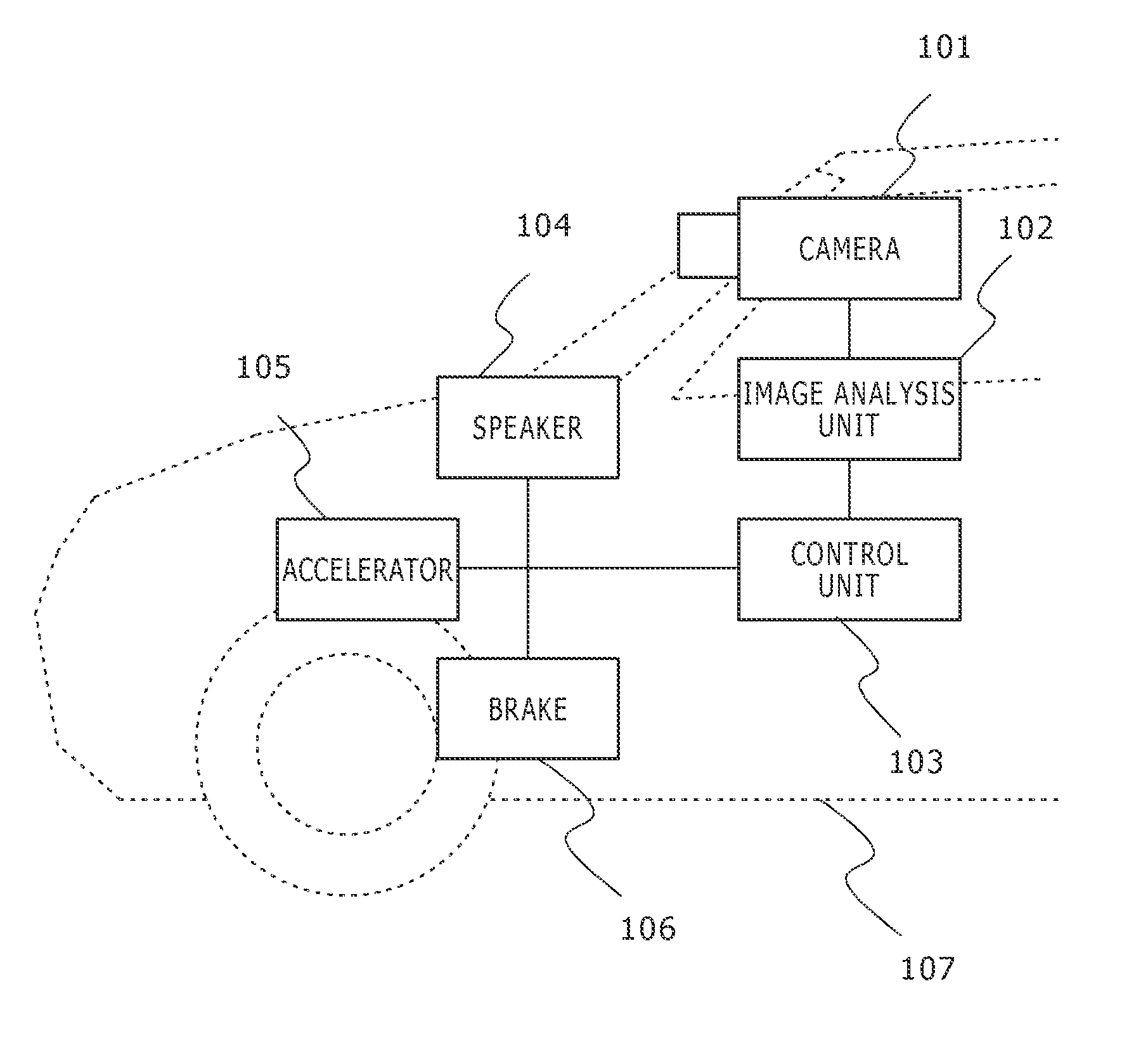
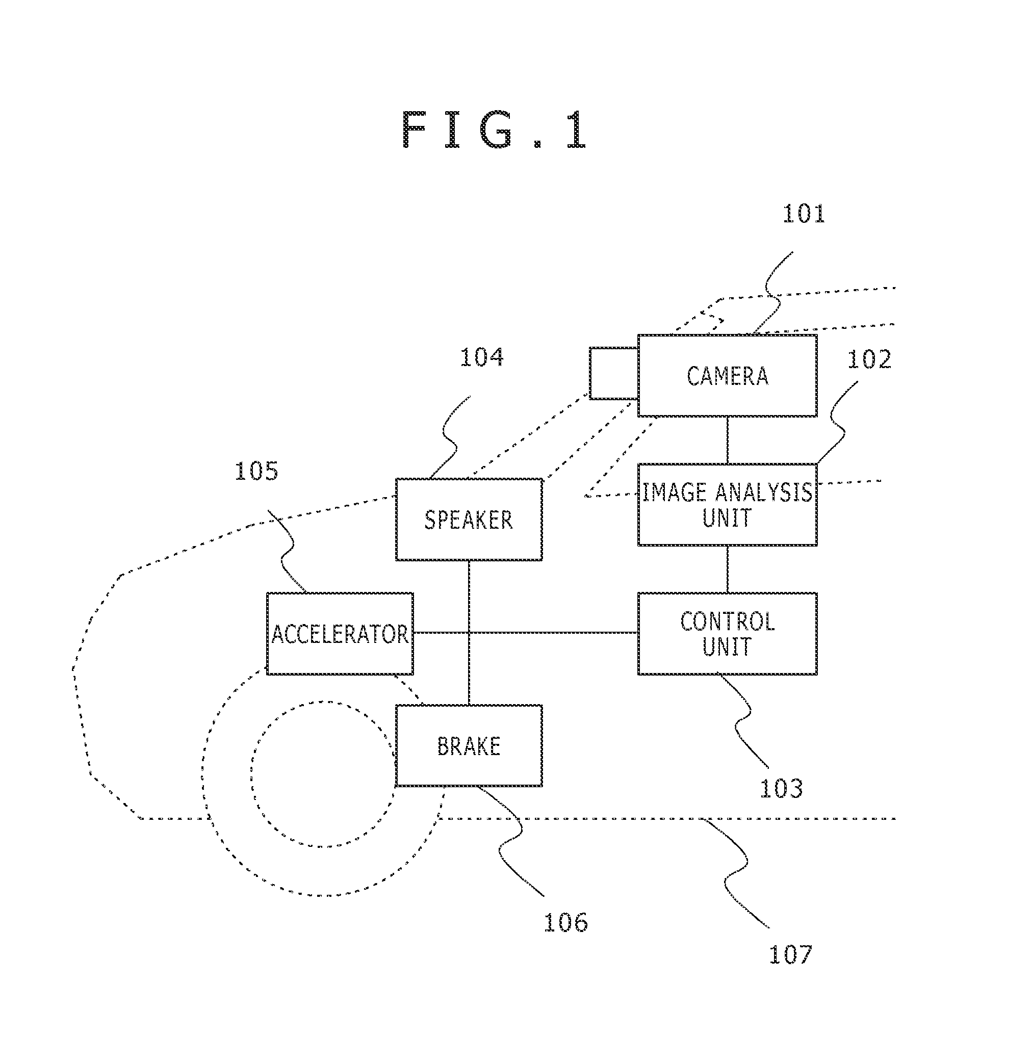
[0019]FIG. 1 shows the outline of the entire configuration for materializing FCW (forward collision control) and / or ACC (adaptive cruise control) according to an embodiment of the present invention. A camera 101, which is an imaging section, is mounted on a vehicle 107 in order for the camera to be able to capture the visual range in front of the vehicle 107. Images in front of the vehicle imaged by the camera101 are input into an image analysis unit 102, which is an image processing section, and the image analysis unit 102 calculates a distance to the preceding vehicle and a relative velocity using the input images in front of the vehicle. Information obtained by the calculation is sent to a control unit 103.

[0020]The control unit 103 determines the degree of risk of collision using the distance to the preceding vehicle and the relative velocity, and issues instructions to give an alarm sound from a speaker 104, to decelerate the vehicle 107 by applying a brake 106, and other instr...


PUM


Abstract

The object of the present invention is to improve the detection capability for detecting a preceding vehicle that may collide with a driver's vehicle using a stereo camera having rolling shutter types of CMOS sensor. The present invention relates to an in-vehicle image processing device that includes: plural imaging sections for imaging the area ahead of a driver's vehicle; an image processing section for detecting another vehicle using disparity information about plural images obtained by the imaging sections. In this case, the imaging sections include imaging devices the exposure timing of each of which is different on the basis of a line of the imaging screen, and the imaging devices are sequentially exposed in the direction from the lowermost edge to the uppermost edge of the another vehicle.

Description

TECHNICAL FIELD[0001]The present invention relates to an in-vehicle image processing device and method that are used for obtaining images around a vehicle and detecting obstacles and the like.BACKGROUND ART[0002]In-vehicle processing for detecting an obstacle in front of a vehicle using an in-vehicle camera has been widely researched and developed as a precautionary safety technology for vehicle. In particular, since a stereo camera, which is disclosed in Patent Literature 1 and uses two cameras, can detect a distance to an obstacle, the stereo camera can be used for building a higher-performance system in comparison with a typical monocular camera, so that a various kinds of application can be materialized.[0003]Since a stereo camera uses two cameras, it becomes important to select a type of imaging device when it is taken into consideration for the stereo camera to be made as a commercial product. A CMOS sensor has an advantage in that it needs a smaller number of components and c...

Claims


Application Information

Patent Timeline
Patent Type & Authority Applications(United States)
IPC IPC(8): H04N7/18H04N5/335B60R1/00H04N5/235
CPCH04N7/181H04N5/2353B60R2300/8093B60R1/00B60R2300/30H04N5/335G08G1/166G02B7/34H04N13/239G06V20/584G06V20/58H04N23/689H04N25/531H04N25/76H04N23/73H04N25/00
Inventor OTSUKA, YUJI
Owner HITACHI AUTOMOTIVE SYST LTD
Why Eureka
Try Eureka