
Lubricating oil composition, and sliding mechanism using lubricating oil composition

a technology of lubricating oil and composition, which is applied in the direction of lubricant composition, mechanical equipment, rotary machine parts, etc., can solve the problems of less likely to achieve fuel consumption saving effect, increase friction coefficient, and inability to achieve friction reduction, etc., to achieve excellent low-friction performance and low friction coefficient

Active Publication Date: 2015-02-05
IDEMITSU KOSAN CO LTD
View PDF3 Cites 7 Cited by
  • Summary
  • Abstract
  • Description
  • Claims
  • Application Information

AI Technical Summary

Benefits of technology

The present invention provides a lubricating oil composition that has a low friction coefficient even when used with low-friction sliding materials. Additionally, the invention provides a sliding mechanism that is still excellent in low-friction performance when combined with a sliding member that has a film of a specific low-friction sliding material on its surface. These technical effects allow for improved performance and efficiency of the lubricating oil composition in various applications using low-friction sliding materials.

Problems solved by technology

However, the friction reducing effect of a DLC material is occasionally small in the presence of a lubricating oil composition, and, in this case, a fuel consumption saving effect is less liable to be obtained.
As in the above, lubricating oil compositions for low-friction sliding materials have been developed; however, even though these techniques are applied, the friction coefficient may increase when ZnDTP is incorporated for further improving abrasion resistance, and there is recognized a phenomenon that could not attain friction reduction.

Method used

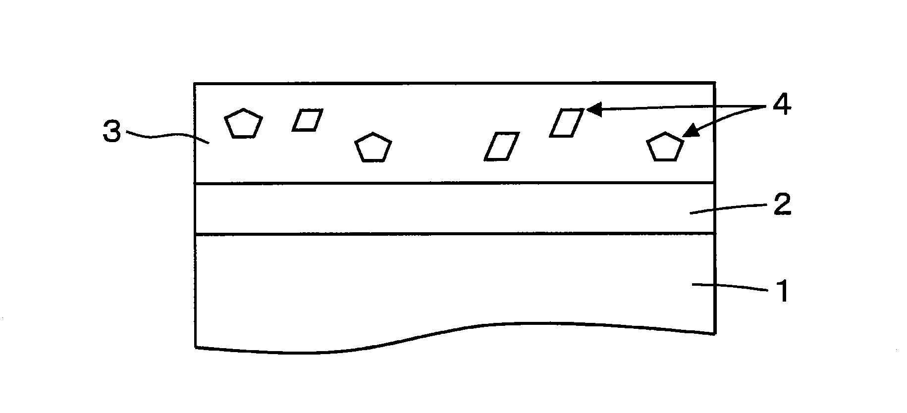
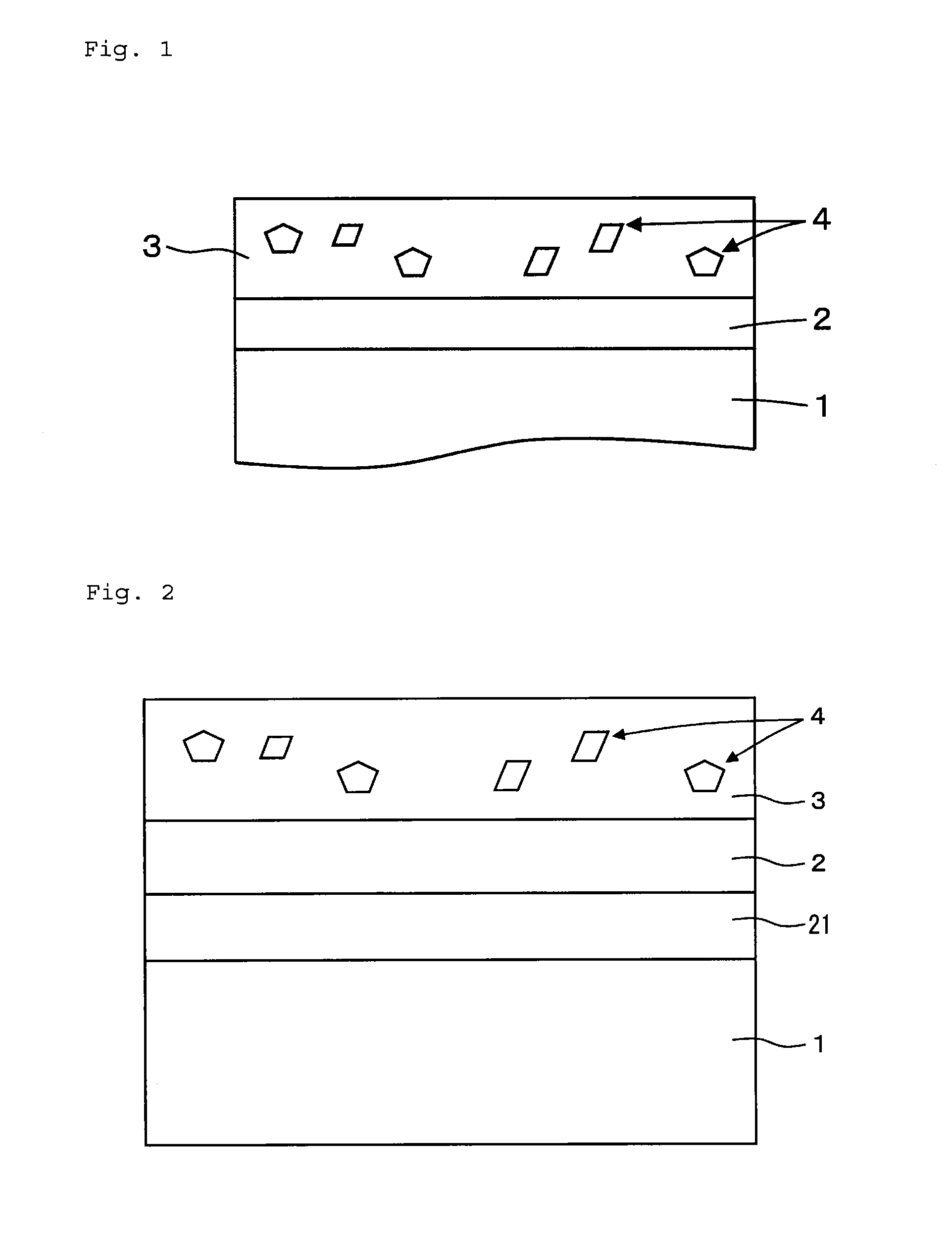
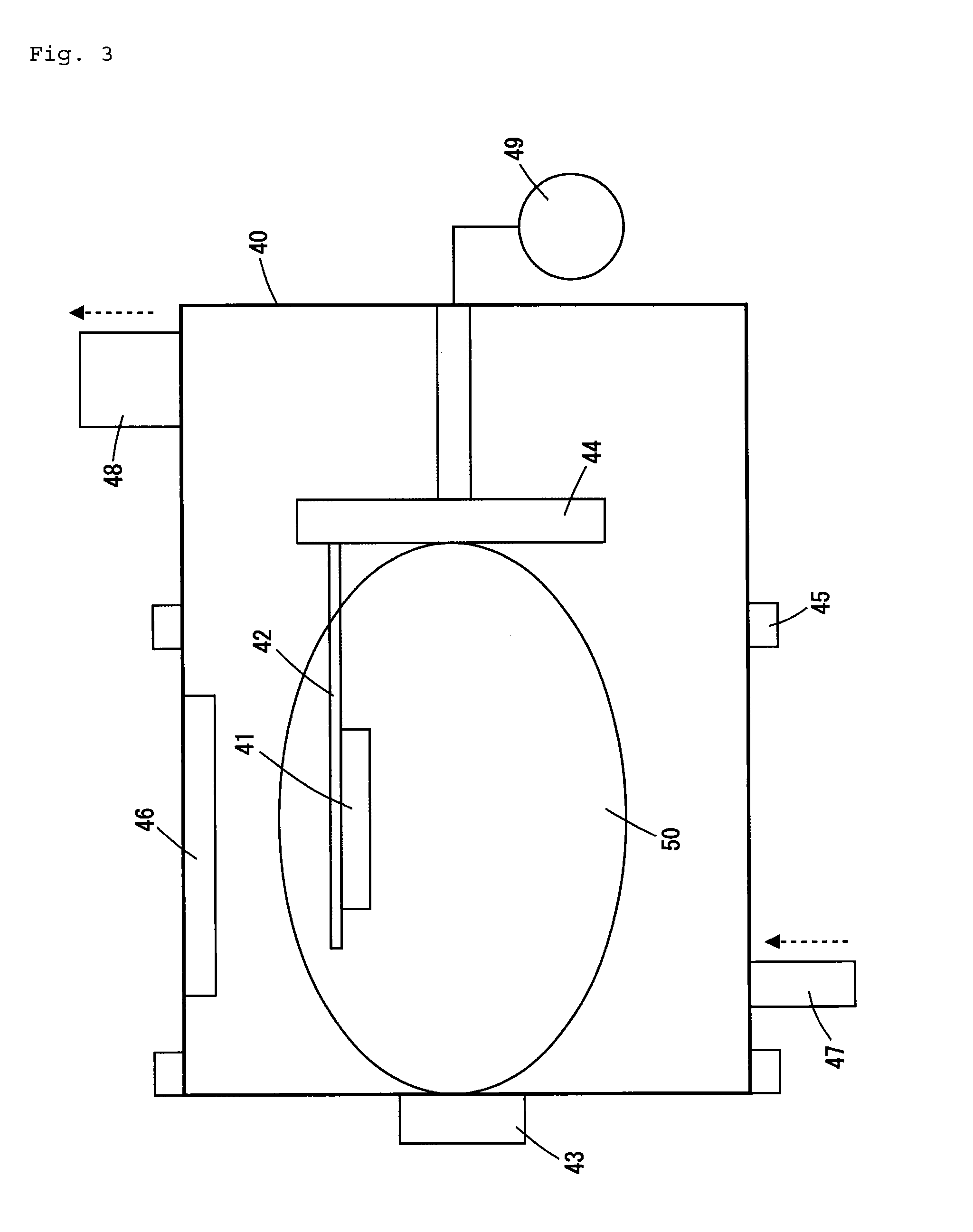

Image

  • Lubricating oil composition, and sliding mechanism using lubricating oil composition
  • Lubricating oil composition, and sliding mechanism using lubricating oil composition
  • Lubricating oil composition, and sliding mechanism using lubricating oil composition

Examples


example

[0122]Next, the present invention will be described in further detail with reference to examples, but the present invention shall by no means be restricted to these examples.

examples 1 , 2

Examples 1, 2 and Comparative Examples 1 to 3

[0123]The lubricating oil compositions comprising the components shown in Table 1 were prepared and subjected to a frictional property test shown below to determine the friction coefficient thereof. The results are shown in Table 1.

[0124]Test Apparatus: TE77 Reciprocating Friction Tester

[0125]Test Pieces:[0126]Test Ball SUJ-2 ball (diameter 10 mm)[0127]Test Plate DLC-coated plate (base material: SUJ-2, 58 mm×38 mm×4 mm)

[0128]Test Condition: load 100 N, temperature 100° C., amplitude 8 mm, frequency 10 Hz

[0129]The DLC-coated disc used here is as follows.

[0130]DLC containing 20 atom % of hydrogen (graphite crystal size 20 nm)

[0131]The intermediate layer of the DLC coating is comprised of a Ti layer, and the total thickness thereof is 3.0 μm.

TABLE 1ExampleComparative Example12123Compoundedhydrorefined base oilbalancebalancebalancebalancebalanceComponentfriction-reducing agent A1.00————(% by mass)friction-reducing agent B—1.00———friction-redu...


PUM

PropertyMeasurementUnit
crystal diameteraaaaaaaaaa
kinematic viscosityaaaaaaaaaa

Abstract

Disclosed is a lubricating oil composition for low-friction sliding materials, which is used in a sliding mechanism where a DLC film containing hydrogen in an amount of from 5 atom % to 50 atom % is formed on at least one sliding surface.The lubricating oil composition contains, in the lubricant base oil therein and based on the total amount of the composition, (A) an organic zinc dithiophosphate in an amount of from 0.005% by mass to 0.12% by mass in terms of the phosphorus concentration therein, (B) an amide-based friction-reducing agent in an amount of from 0.05% by mass to 5.0% by mass, and (C) an alkaline earth metal salicylate-based detergent and / or an alkaline earth metal sulfonate-based detergent in an amount of from 0.05% by mass to 0.5% by mass in terms of the alkaline earth metal concentration therein.

Description

TECHNICAL FIELD[0001]The present invention relates to a lubricating oil composition and a sliding mechanism using the lubricating oil composition, and more precisely relates to a lubricating oil composition that exhibits an extremely low friction coefficient when used as a lubricating oil for low-friction sliding materials, and to a sliding mechanism that uses the lubricating oil composition and exhibits a low friction coefficient.BACKGROUND ART[0002]In recent years, it is important to cope with environmental problems in various fields. Technical development on energy saving and reduction of a discharge amount of carbon dioxide is thus being promoted. For example, it is an important subject to improve the fuel efficiency for vehicles, and for attaining the subject, technological development of lubricating oils and sliding materials is carried out.[0003]As regards development of lubricating oil compositions, various base oils and additives have so far been developed for the purpose o...

Claims


Application Information

Patent Timeline
Patent Type & Authority Applications(United States)
IPC IPC(8): C10M141/10F16C33/04
CPCC10M141/10F16C2206/04F16C33/043C10M163/00C10M2207/262C10M2215/08C10M2219/046C10M2223/045C10M2207/289C10M2209/084C10M2215/082C10M2215/28C10M2219/044C10M2219/068C10N2040/25C10N2080/00C10N2010/12C10N2010/04C10N2060/14C10M141/00
Inventor OGAHARA, YOKOKASAI, MORITSUGUKOSHIMA, HIROAKITSUJIOKA, MASANORIMIYAKE, KOJI
Owner IDEMITSU KOSAN CO LTD
Learn More