Polycrystalline superhard material and method for making same

Active Publication Date: 2015-02-12
ELEMENT SIX LTD
View PDF4 Cites 13 Cited by
  • Summary
  • Abstract
  • Description
  • Claims
  • Application Information

AI Technical Summary

Benefits of technology

[0016]Disclosed example methods may be relatively less complex and or more cost efficient, and di

Problems solved by technology

However, the extreme hardness and abrasion resistance of materials such as PCD or PCBN which are typically used as the cutting element or insert in such applications makes it very

Method used


Image

  • Polycrystalline superhard material and method for making same
  • Polycrystalline superhard material and method for making same

Examples


Example

EXAMPLE 1

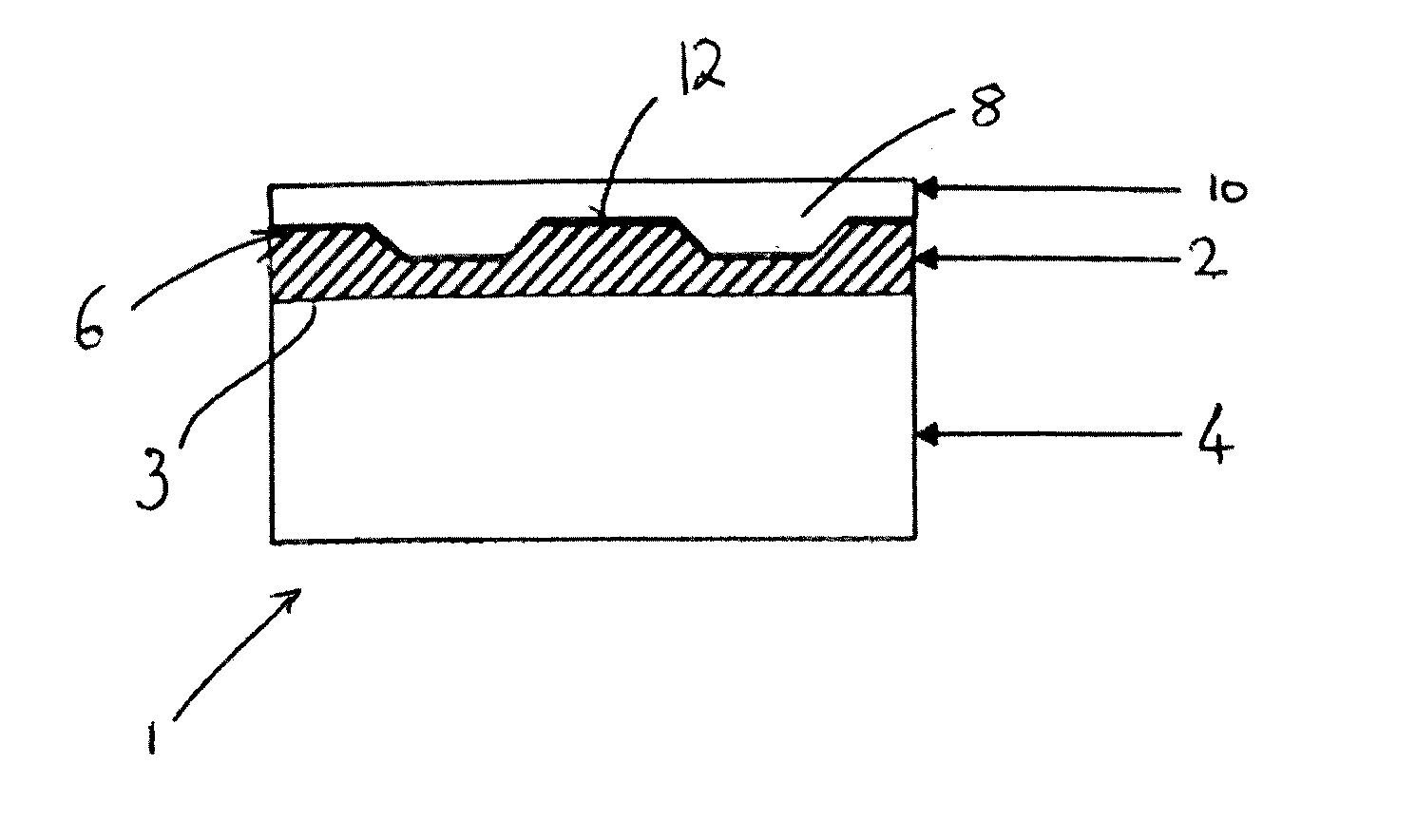
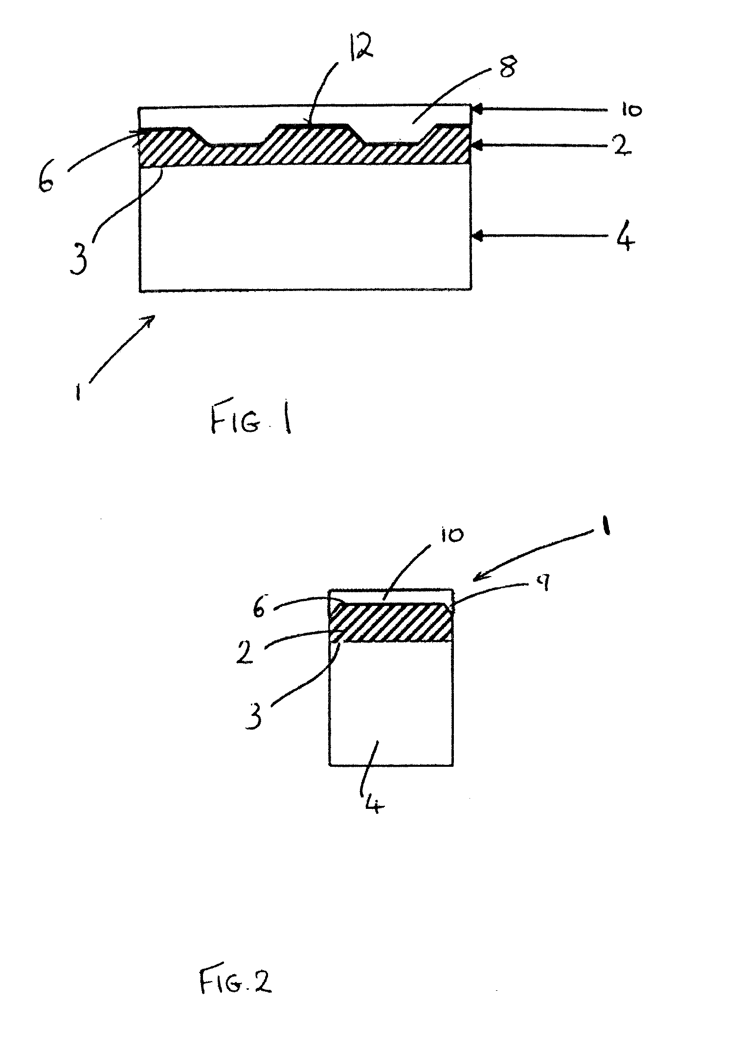
[0048]A surface topology configuration may be designed according to the requirements of a given drilling or machining application and having regard to the intended shape of a cutter structure or machine tool insert. A cobalt-cemented carbide substrate body may be provided and a ceramic plug may be provided, the ceramic plug having a surface comprising a surface topology that is complementary (i.e. inverse) to that of the desired surface topology for the cutter or machine tool insert. A pre-compact assembly may be prepared by forming a plurality of diamond grains into an aggregation against the surface of the substrate, and encapsulating the assembly within a jacket, formed for example of alumina or other ceramic material. The surface of the ceramic plug having the desired surface topology to be imparted to the diamond body on sintering is placed in contact with the diamond grains, as shown in FIGS. 1 and 2. The diamond grains may have a mean size of at least about 1 micron ...

Example

EXAMPLE 2

[0049]A surface topology configuration may be designed according to the requirements of a given machining application and having regard to the intended shape of a machine tool insert. A ceramic body may be provided, having a surface comprising a surface topology that is complementary (i.e. inverse) to that of the desired surface topology for the superhard material. A pre-compact assembly may be prepared by forming a plurality of cubic boron nitride (cBN) grains into an aggregation against the surface of a pre-formed substrate, and encapsulating the assembly within a jacket formed for example of a ceramic material such as alumina. The surface of the ceramic plug having the desired surface topology to be imparted to the body on sintering is placed in contact with the cubic boron nitride (cBN) grains, as shown in FIGS. 1 and 2. The aggregation may also include a blend of powders comprising 86 weight % cBN grains and a binder material comprising 70.0 weight % Al, 11.7 weight % ...


PUM

PropertyMeasurementUnit
Thicknessaaaaaaaaaa
Thicknessaaaaaaaaaa
Thicknessaaaaaaaaaa

Abstract

A method of making a body of polycrystalline superhard material comprising placing an aggregated mass of grains of superhard material into a canister, placing a ceramic layer either in direct contact with the aggregated mass of grains of superhard material or in indirect contact therewith, the ceramic layer being spaced from the grains by an interlayer of material when present, the ceramic layer having a surface with surface topology, the surface topology imprinting a pattern in the aggregated mass of grains of superhard material complementary to the surface topology, the ceramic material and the material of the interlayer being such that they do not react chemically with the superhard material and/or a sinter catalyst material for the grains of superhard material. The aggregated mass of grains of superhard material and ceramic layer are subjected to a pressure of greater than 5.5 GPa and sintered to form a body of polycrystalline superhard material having a surface topology complementary to the surface topology of the ceramic layer. The ceramic layer and interlayer if present are then removed from the body of polycrystalline material. There is also disclosed a body of polycrystalline superhard material having a surface topology on a first surface, the first surface being substantially free of material from a canister used in formation of the body of polycrystalline superhard material.

Description

FIELD[0001]This disclosure relates generally to bodies of polycrystalline super-hard material that may be used, for example, as cutters for drilling in the oil and gas industry or as inserts for machine tools, and to a method for making the same.BACKGROUND[0002]It has been appreciated that cutters and machine tool cutting inserts having cutting surfaces with shaped topologies may be advantageous in various applications as the surface features may be beneficial in use to divert, for example, chips from the working surface being worked on by the cutter or machine tool, and / or in some instances to act as a chip breaker. Also, such surface topologies may produce demonstrably better surface finish qualities compared to flat surface cutting tool geometries. However, the extreme hardness and abrasion resistance of materials such as PCD or PCBN which are typically used as the cutting element or insert in such applications makes it very difficult and expensive to machine these materials with...

Claims


Application Information

Patent Timeline
IPC IPC(8): E21B10/56B23B27/14C01B31/06C04B35/5831C04B35/645
CPCE21B10/56C04B35/5831C04B35/645B23B2226/315B23B27/148B23B2200/32C01B31/06B22F7/08C22C26/00B22F2005/001B22F2005/005B22F2998/10C04B35/52C04B2235/427Y10T407/24B24D3/00B24D18/00B22F3/14B22F3/162B01J3/06
Inventor JONKER, CORNELIS ROELOFNILEN, ROGER WILLIAM NIGELKASONDE, MAWEJAANDERSIN, STIG KE
Owner ELEMENT SIX LTD
Why Eureka
Try Eureka