Method and system for floation separation in a magnetically controllable and steerable medium

Active Publication Date: 2015-02-12
CIDRA CORP SERVICES
View PDF2 Cites 20 Cited by
  • Summary
  • Abstract
  • Description
  • Claims
  • Application Information

AI Technical Summary

Benefits of technology

[0064]According to some embodiments, the present invention may take the form of synthetic flotation bubbles, using a concept such as incorporating air bubbles into polymer blocks, which are designed to attract or attach mineral rich ore onto their surface and then float to the top of the flotation tank. It is

Problems solved by technology

If the froth is insufficiently stable, or the residence time is too long, the bubbles can break and drop the hydrophobic mineral particles back into the slurry, reducing the effectiveness of the process.
While flotation cell designs aim to optimize this process, the hydro-dynamics of the cell can produce regions where the froth resid

Method used


Image

  • Method and system for floation separation in a magnetically controllable and steerable medium
  • Method and system for floation separation in a magnetically controllable and steerable medium
  • Method and system for floation separation in a magnetically controllable and steerable medium

Examples


Embodiment Construction

FIGS. 1a-1f

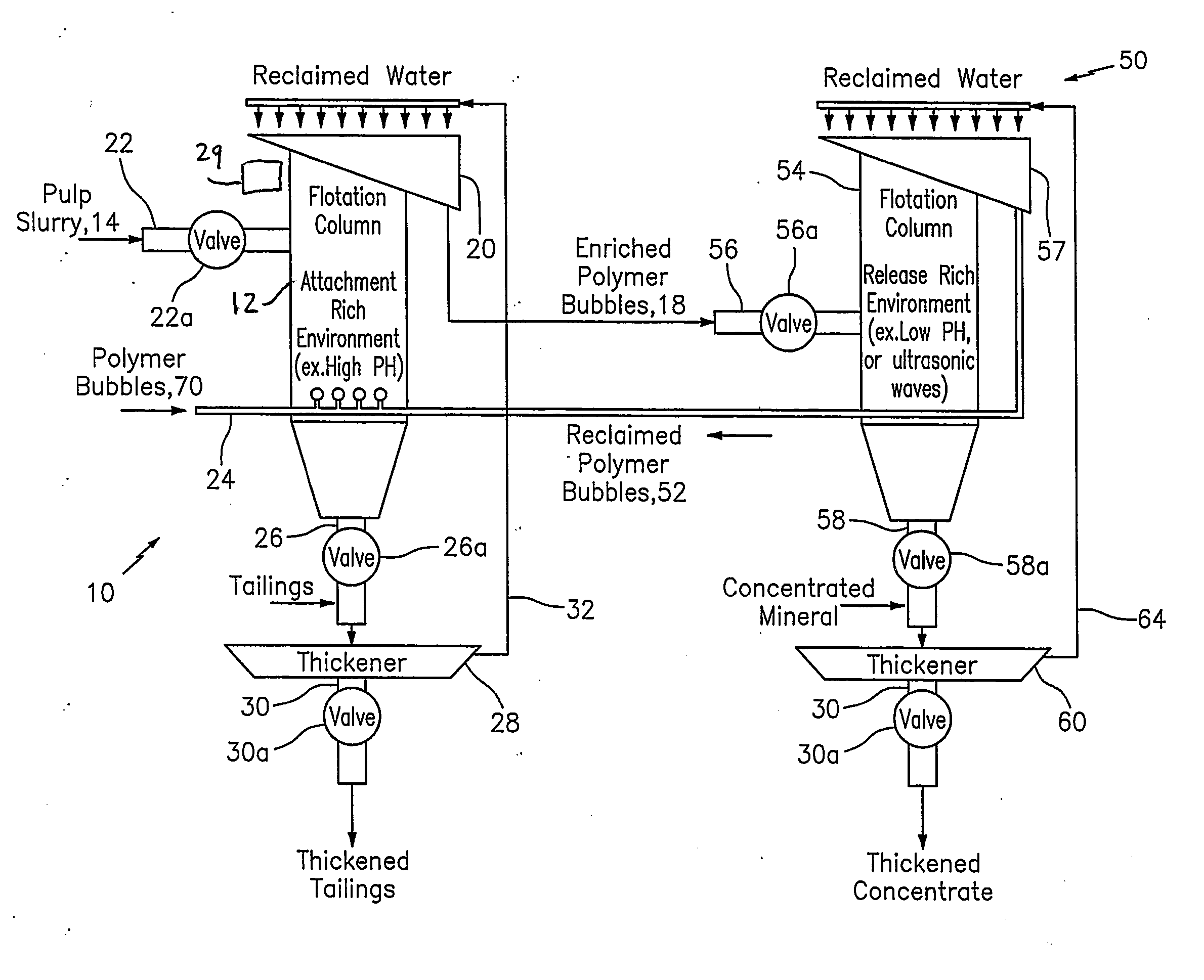
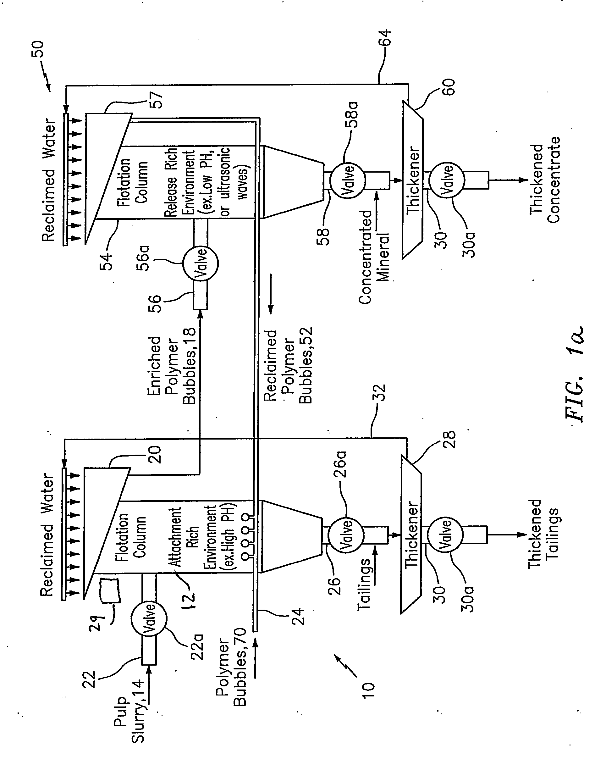
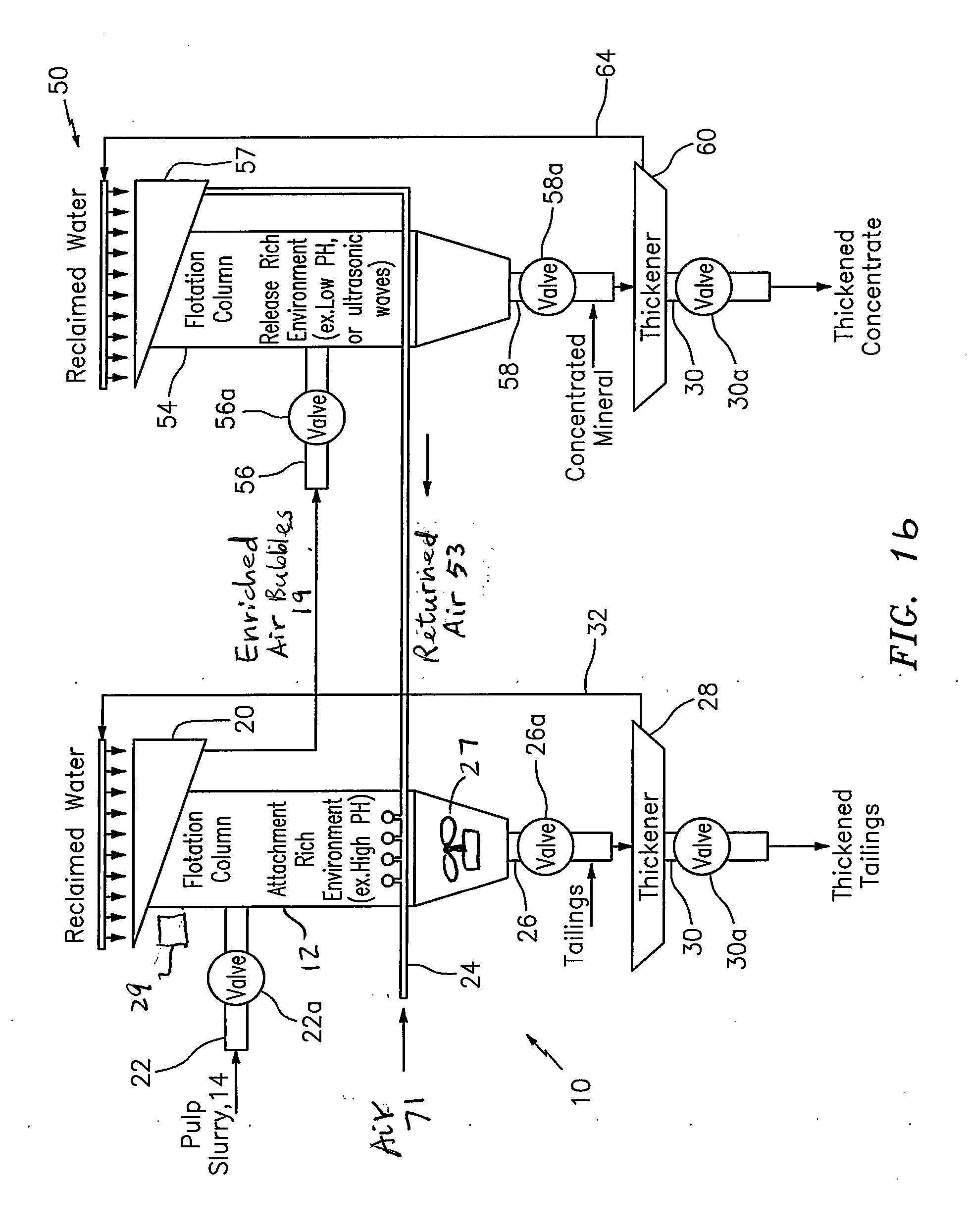
[0132]By way of example, FIG. 1a shows the present invention is the form of apparatus 10, having a flotation cell or column 12 configured to receive a mixture of fluid (e.g. water), valuable material and unwanted material, e.g., a pulp slurry 14; receive synthetic bubbles or beads 70 (FIG. 3a to FIG. 5d) that are constructed to be buoyant when submerged in the pulp slurry or mixture 14 and functionalized to control the chemistry of a process being performed in the flotation cell or column, including to attach to the valuable material in the pulp slurry or mixture 14; and provide enriched synthetic bubbles or beads 18 having the valuable material attached thereon. The terms “synthetic bubbles or beads” and “polymer bubbles or beads” are used interchangeably in this disclosure. The terms “valuable material”, “valuable mineral” and “mineral particle” are also used interchangeably. By way of example, the synthetic bubbles or beads 70 may be made from polymer or polymer-based...


PUM


Abstract

The present invention provides new techniques related to magnetically controllable and/or steerable froth for use in separation processes of mineral-bearing ore and bitumen. Apparatus is provided featuring a processor configured to contain a fluidic medium having a material-of-interest and also having a surfactant with magnetic properties so as to cause the formation of a froth layer that contains at least some of the material-of-interest and is magnetically responsive; and a magnetic field generator configured to generate a magnetic field and provide non-mechanical mixing and steering/driving of the froth layer in the processor. The material-of-interest may be mineral-bearing ore particles or bitumen. The processor includes a flotation tank, a primary separation vessel (PSV), or a pipe, including a tailings pipeline. The pipe has a non-magnetic pipe section, and the magnetic field generator includes a magnetic coil arranged in relation to non-magnetic pipe section to generate the magnetic field and provide the non-mechanical mixing and steering/driving of the froth layer in the pipe.

Description

CROSS-REFERENCE TO RELATED PATENT APPLICATIONS[0001]The present application claims the benefit of U.S. Provisional Patent Application No. 61 / 604,088, filed 28 Feb. 2012, and U.S. Provisional Patent Application No. 61 / 616,604, filed Mar. 28, 2012, which are both incorporated by reference herein in their entirety.[0002]This application is also related to the following nine PCT applications, which are all concurrently filed on 25 May 2012 as follows:[0003]PCT application no. PCT / US12 / 39591 (Atty docket no. 712-002.383), entitled “Method and system for releasing mineral from synthetic bubbles and beads,”[0004]PCT application no. PCT / US12 / 39528 (Atty docket no. 712-002.356-1), entitled “Flotation separation using lightweight synthetic bubbles and beads;”[0005]PCT application no. PCT / US12 / 39524 (Atty docket no. 712-002.359-1), entitled “Mineral separation using functionalized polymer membranes;”[0006]PCT application no. PCT / US12 / 39540 (Atty docket no. 712-002.359-2), entitled “Mineral sep...

Claims


Application Information

Patent Timeline
IPC IPC(8): C10G1/04
CPCC10G1/04B03D1/02B03D1/023B03D1/028B03D1/082B03D1/1456B03D1/1475B03D1/18B03D1/22B03D1/24B03D2203/006
Inventor KERSEY, ALAN D.
Owner CIDRA CORP SERVICES
Why Eureka
Try Eureka