
Surface Processing System for a Work Piece

a surface processing and work piece technology, applied in the direction of grinding feeders, grinding machine components, manufacturing tools, etc., can solve the problems of human health hazards, parts cannot be processed with special machine tools, and parts cannot be processed by special machines, so as to ensure the uniformity of each work piece, the polishing precision of the work piece, and the production efficiency of the work piece.

Inactive Publication Date: 2015-02-12
TAIZHOU FEDERAL ROBOT TECH
View PDF8 Cites 40 Cited by
  • Summary
  • Abstract
  • Description
  • Claims
  • Application Information

AI Technical Summary

Benefits of technology

The patent describes a system that uses a manipulator to process work pieces. By keeping the work piece still and controlling the manipulator accurately, each work piece can be processed with high precision and efficiency. Additionally, the system has a finishing means that automatically completes the work piece, improving automation and saving time and labor.

Problems solved by technology

Some problems may exist in the casting shape and machining size for components of complex appearance, particularly water faucets for bathrooms, including deviation, variation on wall thickness and inconsistency in shapes and positions, for which the components could not be processed by special machine tools.
As heat will be generated by finishing and friction and a large amount of metallic dust will be produced in the process of finishing, such working conditions are harmful to humans.
Moreover, thanks to instability of manual operation, the finishing depth can not be easily and precisely determined.
Consequently, low operation efficiency is resulted and the uniformity and stability of polishing products could not be sufficiently guaranteed.
Moreover, the ordinary finishing and polishing mechanisms are too simple to achieve grinding on various complex curved surfaces from multiple axial directions, orientations and angles.
Therefore, the existing finishing and polishing mechanisms could be used for efficient and precise processing and mostly have to depend on rough grinding by technicians, for which the polishing effect for various work pieces could not be guaranteed.
Moreover, in the filed of polishers, the work piece generally could not be positioned precisely as a result of defects of the structure of equipment, and the work piece usually has to be grasped by hands when the work piece is being finished.

Method used


Image

  • Surface Processing System for a Work Piece
  • Surface Processing System for a Work Piece
  • Surface Processing System for a Work Piece

Examples


first embodiment

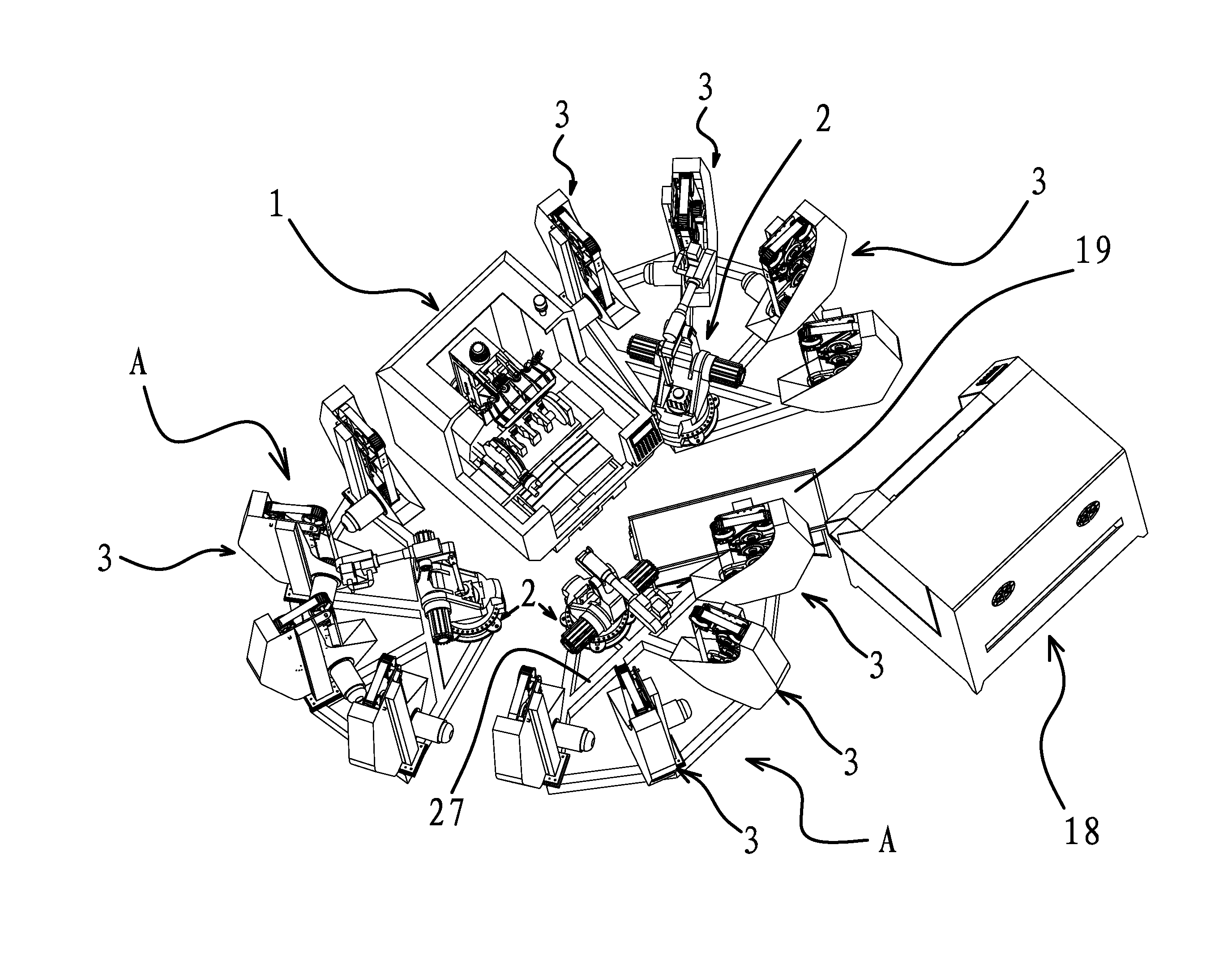
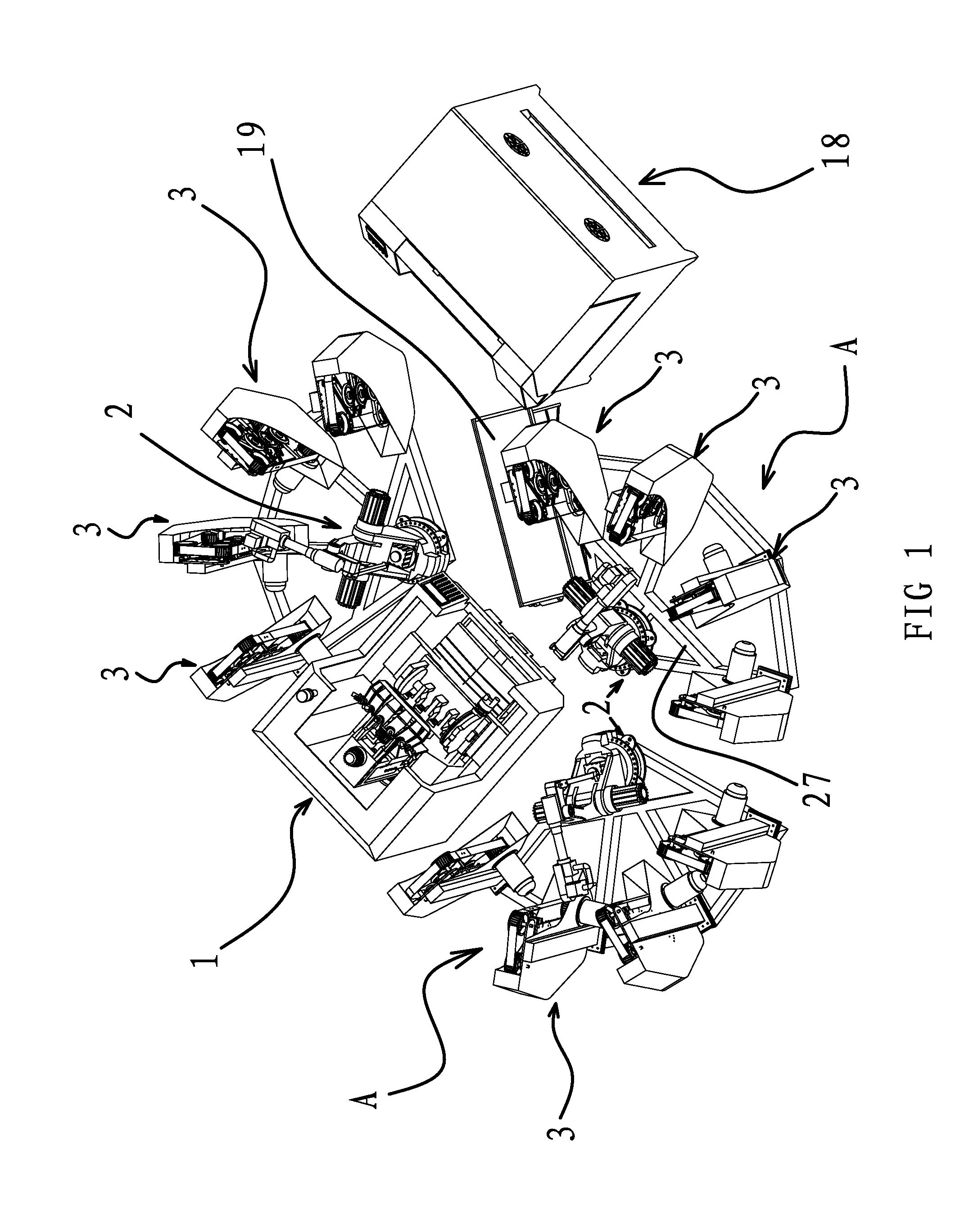
[0048]As shown in FIG. 10, a surface processing system for a work piece is disposed on the side of the processing center 1 for machining the work piece. The work piece to be processed could be a valve, a water faucet or a pipe. All the work pieces share a common feature that the work piece has an inner hole for being held by the manipulator. The system includes three groups of polishing unit A which are evenly distributed around the processing unit 1, and storage hoppers for containing processed work pieces are placed around each polishing unit A. A manipulator 2 and several polishers 3 having different polishing precisions are provided on the polishing unit A. In particular, four polishers 3 are arranged in sequence around the manipulator 2 and the manipulator 2 could move the work piece between the processing center 1 and the polishing unit A. When the manipulator 2 is located at the processing unit 1, the manipulator 2 loads all the machined work pieces at one time. When the mani...

second embodiment

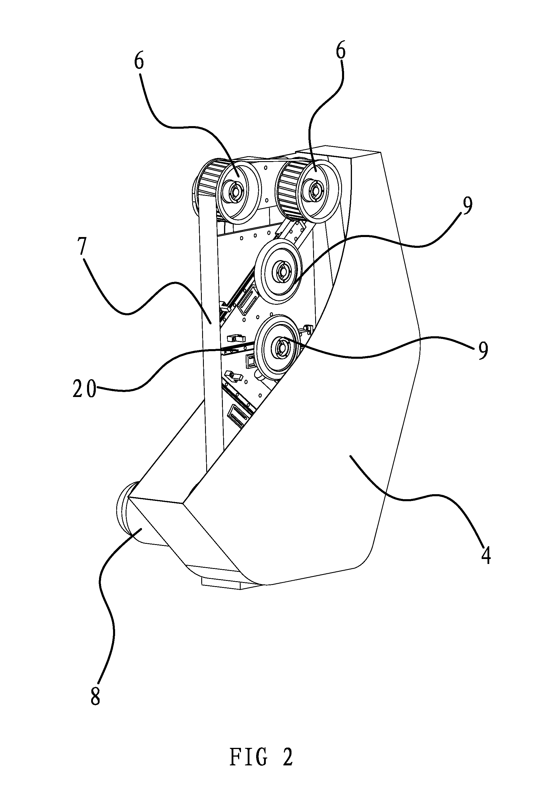
[0062]As shown in FIG. 1, a surface processing system for a work piece is disposed on the side of the processing center 1 for machining the work piece. The system includes polishing units A, a finishing means 18 and a conveyer belt 19 provided between the polishing unit and the finishing means 18, which could drive the work piece to move horizontally. In particular, there are three polishing units A evenly distributed around the processing unit 1. A manipulator 2 and four polishers 3 having different polishing precisions are provided on each polishing unit A. A mounting support 27 is disposed in each polishing unit A, and the manipulator 2 and each polisher 3 are mounted on the mounting support 27. The mounting support 27 is in the shape of a sector. The manipulator 2 is fixed at the center of the sector of the mounting support 27. All the polishers 3 are evenly distributed on the arc edge of the sector of the mounting support 27. The work piece could be moved by the manipulator 2 b...


PUM


Abstract

The present invention provides a surface processing system for a work piece in the mechanical technical field. The system comprises at least one group of polishing units. A manipulator and several polishers with different polishing precisions are provided on the polishing units. The polishers are arranged around the manipulator in turn. The work piece could be moved by the manipulator between the processing center and the polishing units. The machined work piece is loaded by the manipulator for one time when the manipulator is located at the processing center. When the manipulator is located at the polishing units, the manipulator keeps holding the work piece and transfers the work piece in a preset sequence to each polisher corresponding to the polishing unit where the manipulator is located. The surface of work pieces having different wall thicknesses and complex surfaces could be processed in a large batch with a high efficiency.

Description

BACKGROUND OF THE INVENTION[0001]1. Field of Invention[0002]The present invention relates to a surface processing system in the polishing technical field, and in particular, to the surface processing treatment for a work piece, including a valve, a water pipe and, a water faucet.[0003]2. Related Art[0004]In the manufacturing industry, in order to protect the quality and aesthetic appearance of the products, polishing and finishing of the work piece are important processes for molding of components. Some problems may exist in the casting shape and machining size for components of complex appearance, particularly water faucets for bathrooms, including deviation, variation on wall thickness and inconsistency in shapes and positions, for which the components could not be processed by special machine tools. Therefore, man power will required for processing on abrasive belt machine and cloth wheel machine. As heat will be generated by finishing and friction and a large amount of metallic ...

Claims


Application Information

Patent Timeline
IPC IPC(8): B24B27/00B24B21/00
CPCB24B27/0076B24B21/006B24B27/0069B24B21/008B24B27/0023B24B21/12B24B21/20B24B41/005B24B41/06B24B55/04B23Q7/047B23Q39/027B25J11/0065B24B21/16
Inventor CHEN, QIYUE
Owner TAIZHOU FEDERAL ROBOT TECH
Learn More