Eureka AIR delivers breakthrough ideas for toughest innovation challenges, trusted by R&D personnel around the world.

Parallel path, downdraft gasifier apparatus and method

a gasifier and parallel path technology, applied in the field of parallel path and downdraft gasifier apparatus and method, can solve the problem of fast continuous increase in fuel cost, and achieve the effect of individual, rapid and precise control of the environment, and greater control in the initial phas

Active Publication Date: 2015-02-26
STRATEAN
View PDF4 Cites 4 Cited by
  • Summary
  • Abstract
  • Description
  • Claims
  • Application Information

AI Technical Summary

Benefits of technology

This patent describes a gasifier system for gasifying biomass. The gasifier system has a refractory stack with multiple sections to improve heat retention and durability. It also has an enclosed top to prevent the entry of nitrogen and maintain desired temperatures. The gasifier system includes a mixing blade to improve drying and to remove dead or stagnant zones. The system also has individual control of the oxidation and reduction zones, and a heater to increase control and reduce production time. The gasifier system is designed to optimize gasification processes and improve production efficiency.

Problems solved by technology

However, beginning with the oil embargo of the 1970's, there has been an almost continual increase in the cost of fuel.

Method used


Image

  • Parallel path, downdraft gasifier apparatus and method
  • Parallel path, downdraft gasifier apparatus and method
  • Parallel path, downdraft gasifier apparatus and method

Examples


Embodiment Construction

[0051]It will be readily understood that the components of the present invention, as generally described and illustrated in the drawings herein, could be arranged and designed in a wide variety of different configurations. Thus, the following more detailed description of the embodiments of the system and method of the present invention, as represented in the drawings, is not intended to limit the scope of the invention, as claimed, but is merely representative of various embodiments of the invention. The illustrated embodiments of the invention will be best understood by reference to the drawings, wherein like parts are designated by like numerals throughout.

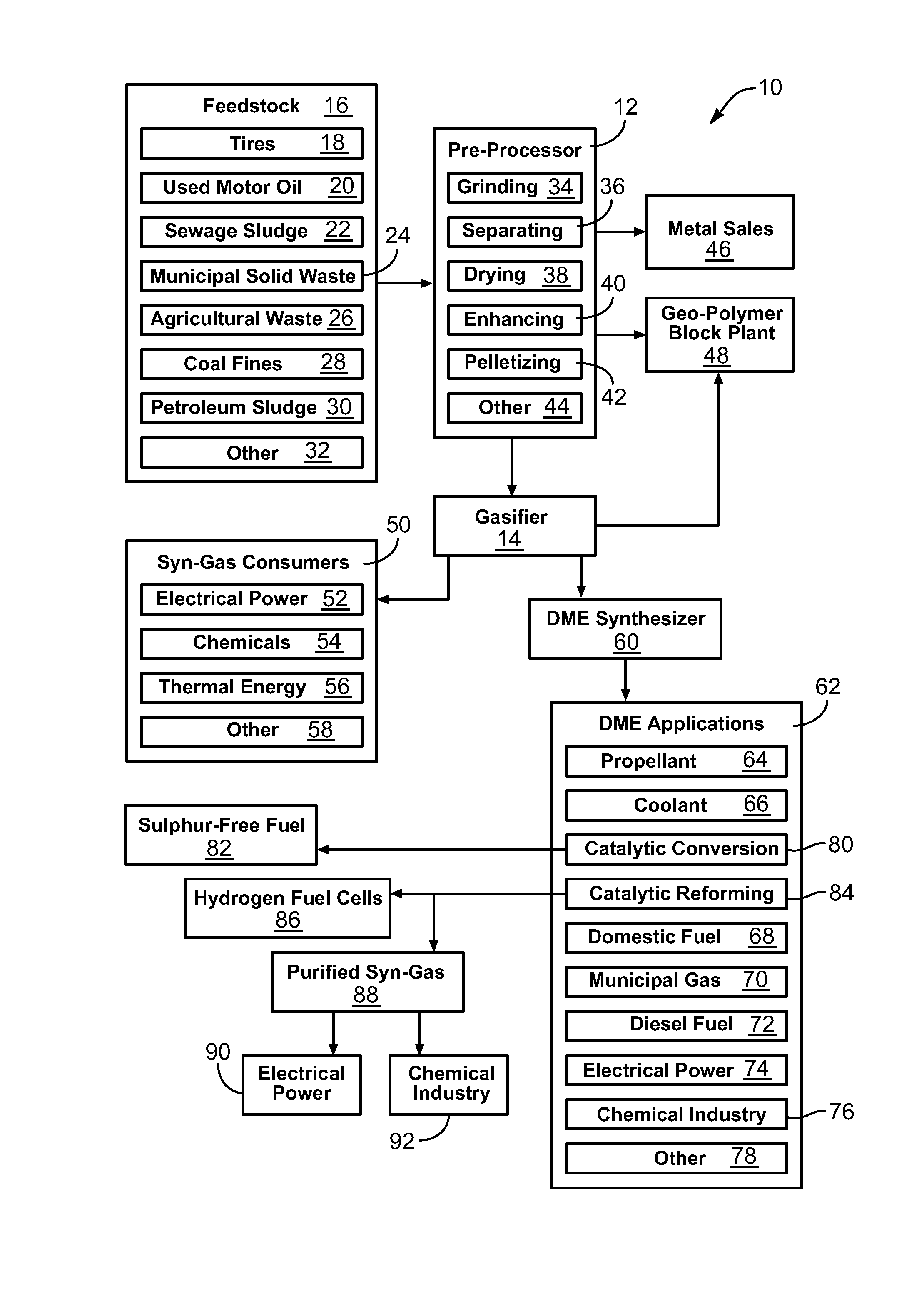
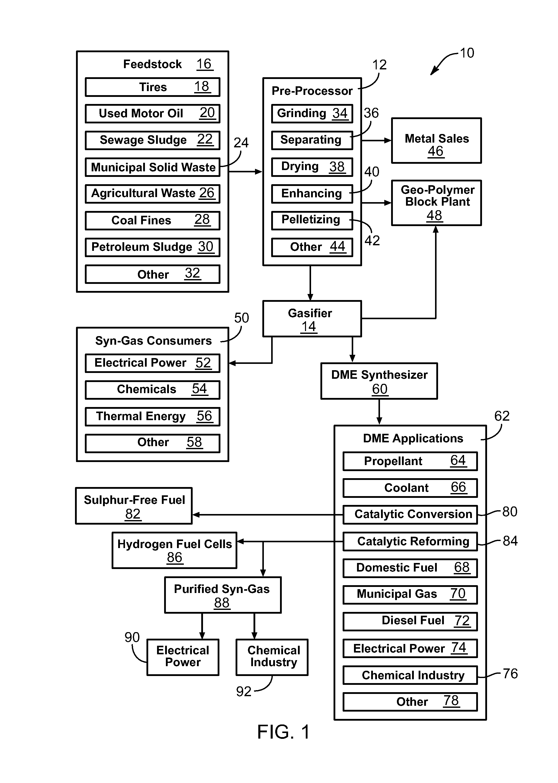
[0052]Referring to FIG. 1, every year, large quantities of municipal solid waste (MSW) are collected for disposal. While most of the materials found within MSW can be recycled in some manner, the costs of recycling the different materials can vary greatly. It is currently feasible to recycle only a portion of the MSW generated. ...


PUM


Abstract

A method for using a downdraft gasifier comprising a housing and a refractory stack contained within the housing. The refractory stack may comprise various sections. Apertures in the sections may be aligned to form multiple columnar cavities. Each columnar cavity may comprise an individual oxidation zone. The method of use may include the steps of placing a feedstock into an upper portion of the refractory stack, measuring the temperature of each columnar cavity, and adjusting the flow of oxygen to a particular columnar cavity to maintain the temperature of the particular columnar cavity within a particular range.

Description

RELATED APPLICATIONS[0001]This application is a continuation of U.S. patent application Ser. No. 12 / 170,421 filed Jul. 9, 2008, which claims the benefit of co-pending U.S. Provisional Patent Application Ser. No. 60 / 948,950 filed Jul. 10, 2007. Both U.S. patent application Ser. No. 12 / 170,421 and U.S. Provisional Patent Application Ser. No. 60 / 948,950 are hereby incorporated by reference.BACKGROUND[0002]1. The Field of the Invention[0003]This invention relates to fuel generation and, more particularly, to novel systems and methods for gasification of municipal solid waste and other feedstocks.[0004]2. The Background Art[0005]Manufactured gas, or synthesis gas (syn-gas) as it is more often called today, comprises the unburned gasses (carbon monoxide and hydrogen gas) created by incomplete combustion of an organic raw material. Gasification (the process of generating manufactured gas) was discovered independently in both France and England. By 1850, gasification of coal had developed t...

Claims


Application Information

Patent Timeline
IPC IPC(8): C10J3/72
CPCC10J3/725C10J2200/36C10J2300/1846C10J3/26C01B3/02C10J3/32C10J3/34C10J3/36C10J3/723C10J3/82C10J2300/0906C10J2300/0946C10J2300/0956C10J2300/0959C10J2300/1276C10J2300/1643C10J2300/1656Y02E20/18
Inventor NEVES, ALAN M.BROCKBANK, GROVER R.EBELING, MORRIS K.
Owner STRATEAN
Why Eureka
Eureka Blog
Learn More