Parallel path, downdraft gasifier apparatus and method

a gasifier and parallel path technology, applied in the field of parallel path and downdraft gasifier apparatus and method, can solve the problem of almost continuous increase in fuel cost, and achieve the effect of individual, rapid and precise control of the environment, and greater control in initiating

Active Publication Date: 2009-05-14
STRATEAN
View PDF23 Cites 24 Cited by
  • Summary
  • Abstract
  • Description
  • Claims
  • Application Information

AI Technical Summary

Benefits of technology

[0016]Each columnar cavity may act as an independent oxidation zone and have a dedicated heater, dedicated gas ports, and dedicated temperature sensors. These heaters, ports, and sensors may be positioned within or proximate the apertures defining the columnar cavities. Thus, the narrowness of the cavities and the positioning of the heaters, ports, and sensors may support individual, rapid, and precise control of the environment within each columnar cavity.
[0017]In selected embodiments, the various apertures aligning to form the columnar cavities may not be exactly cylindrical. For example, the apertures in selected sections may be somewhat conical in shape, converging when viewed with respect to the downward flow of the feedstock. Apertures so configured may create one or more lips or overhangs within the columnar cavities. Tucked on the underside of such overhangs may be grooves. These grooves may extend the circumference of the columnar cavities. Certain grooves may be used to distribute gas (e.g., oxygen) around a circumference of a columnar cavity. Other grooves may house and protect a heater. Accordingly, a heater may extend circumferentially around a columnar cavity. A heater may provide greater control in initiating and automating the gasification process. Additionally, a heater may reduce the amount of time required to bring a gasifier into optimal production.

Problems solved by technology

However, beginning with the oil embargo of the 1970's, there has been an almost continual increase in the cost of fuel.

Method used


Image

  • Parallel path, downdraft gasifier apparatus and method
  • Parallel path, downdraft gasifier apparatus and method
  • Parallel path, downdraft gasifier apparatus and method

Examples


Embodiment Construction

[0049]It will be readily understood that the components of the present invention, as generally described and illustrated in the drawings herein, could be arranged and designed in a wide variety of different configurations. Thus, the following more detailed description of the embodiments of the system and method of the present invention, as represented in the drawings, is not intended to limit the scope of the invention, as claimed, but is merely representative of various embodiments of the invention. The illustrated embodiments of the invention will be best understood by reference to the drawings, wherein like parts are designated by like numerals throughout.

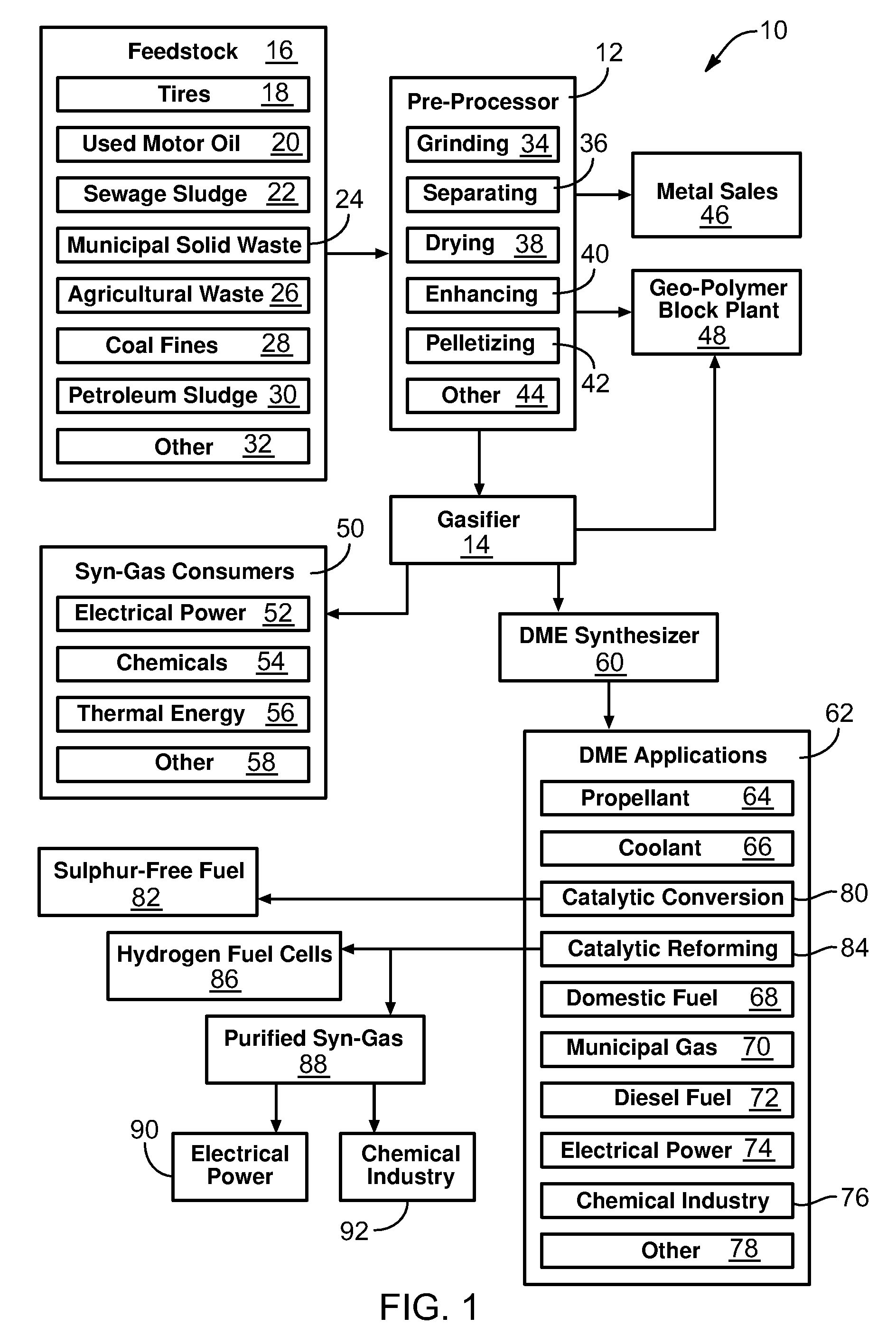
[0050]Referring to FIG. 1, every year, large quantities of municipal solid waste (MSW) are collected for disposal. While most of the materials found within MSW can be recycled in some manner, the costs of recycling the different materials can vary greatly. It is currently feasible to recycle only a portion of the MSW generated. ...


PUM

PropertyMeasurementUnit
lengthaaaaaaaaaa
aspect ratioaaaaaaaaaa

Abstract

A method for using a downdraft gasifier comprising a housing and a refractory stack contained within the housing. The refractory stack may comprise various sections. Apertures in the sections may be aligned to form multiple columnar cavities. Each columnar cavity may comprise an individual oxidation zone. The method of use may include the steps of placing a feedstock into an upper portion of the refractory stack, measuring the temperature of each columnar cavity, and adjusting the flow of oxygen to a particular columnar cavity to maintain the temperature of the particular columnar cavity within a particular range.

Description

1. RELATED APPLICATIONS[0001]This application claims the benefit of co-pending U.S. Provisional Patent Application Ser. No. 60 / 948,950 filed Jul. 10, 2007.2. THE FIELD OF THE INVENTION[0002]This invention relates to fuel generation and, more particularly, to novel systems and methods for gasification of municipal solid waste and other feedstocks.3. THE BACKGROUND ART[0003]Manufactured gas, or synthesis gas (syn-gas) as it is more often called today, comprises the unburned gasses (carbon monoxide and hydrogen gas) created by incomplete combustion of an organic raw material. Gasification (the process of generating manufactured gas) was discovered independently in both France and England. By 1850, gasification of coal had developed to where much of London was lit with manufactured gas, “town gas,” or “coal gas” as it was called. By 1920, many towns and cities throughout the United States supplied manufactured gas to their residents through local “gasworks.”[0004]Following 1930, as natu...

Claims


Application Information

Patent Timeline
Patent Type & Authority Applications(United States)
IPC IPC(8): C10J3/46
CPCC10J3/26Y02E50/32C10J3/74C10J3/86C10J2200/09C10J2300/0903C10J2300/0909C10J2300/0923C10J2300/093C10J2300/0936C10J2300/0946C10J2300/0956C10J2300/0959C10J2300/165C10J2300/1659C10J2300/1671Y02E20/18C10J3/723Y02E50/30
Inventor NEVES, ALAN M.BROCKBANK, GROVER R.EBELING, JR., MORRIS K.
Owner STRATEAN
Why Eureka
Try Eureka