Mirror for the EUV Wavelength Range, Method for Producing such a Mirror, and Projection Exposure Apparatus Comprising such a Mirror

Active Publication Date: 2015-02-26
CARL ZEISS SMT GMBH
View PDF2 Cites 8 Cited by
  • Summary
  • Abstract
  • Description
  • Claims
  • Application Information

AI Technical Summary

Benefits of technology

[0011]It is an object of the invention to provide a mirror for the EUV wavelength range which has a high

Problems solved by technology

In this respect, the doping not only increases the radiation resistance

Method used


Image

  • Mirror for the EUV Wavelength Range, Method for Producing such a Mirror, and Projection Exposure Apparatus Comprising such a Mirror
  • Mirror for the EUV Wavelength Range, Method for Producing such a Mirror, and Projection Exposure Apparatus Comprising such a Mirror
  • Mirror for the EUV Wavelength Range, Method for Producing such a Mirror, and Projection Exposure Apparatus Comprising such a Mirror

Examples


Example

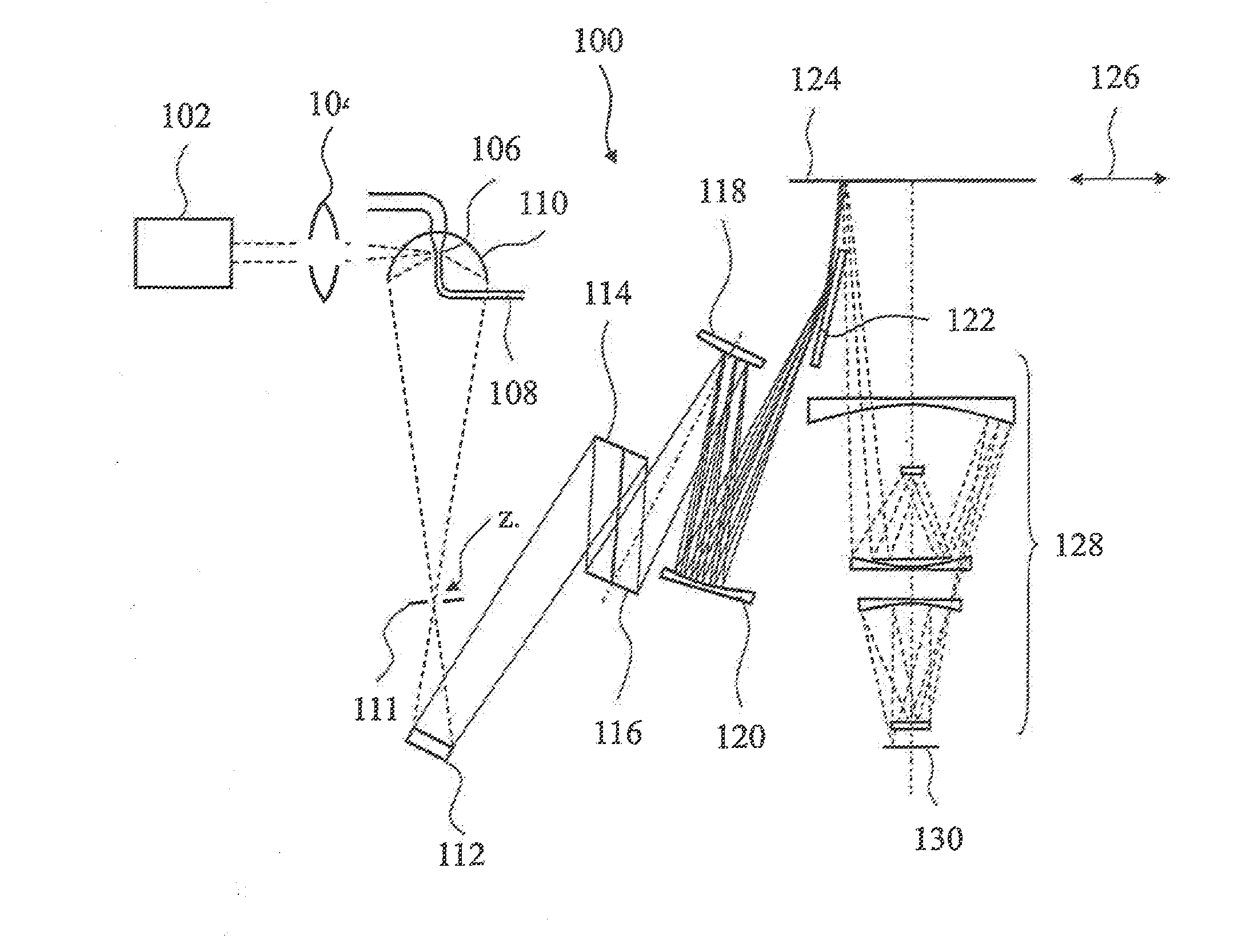
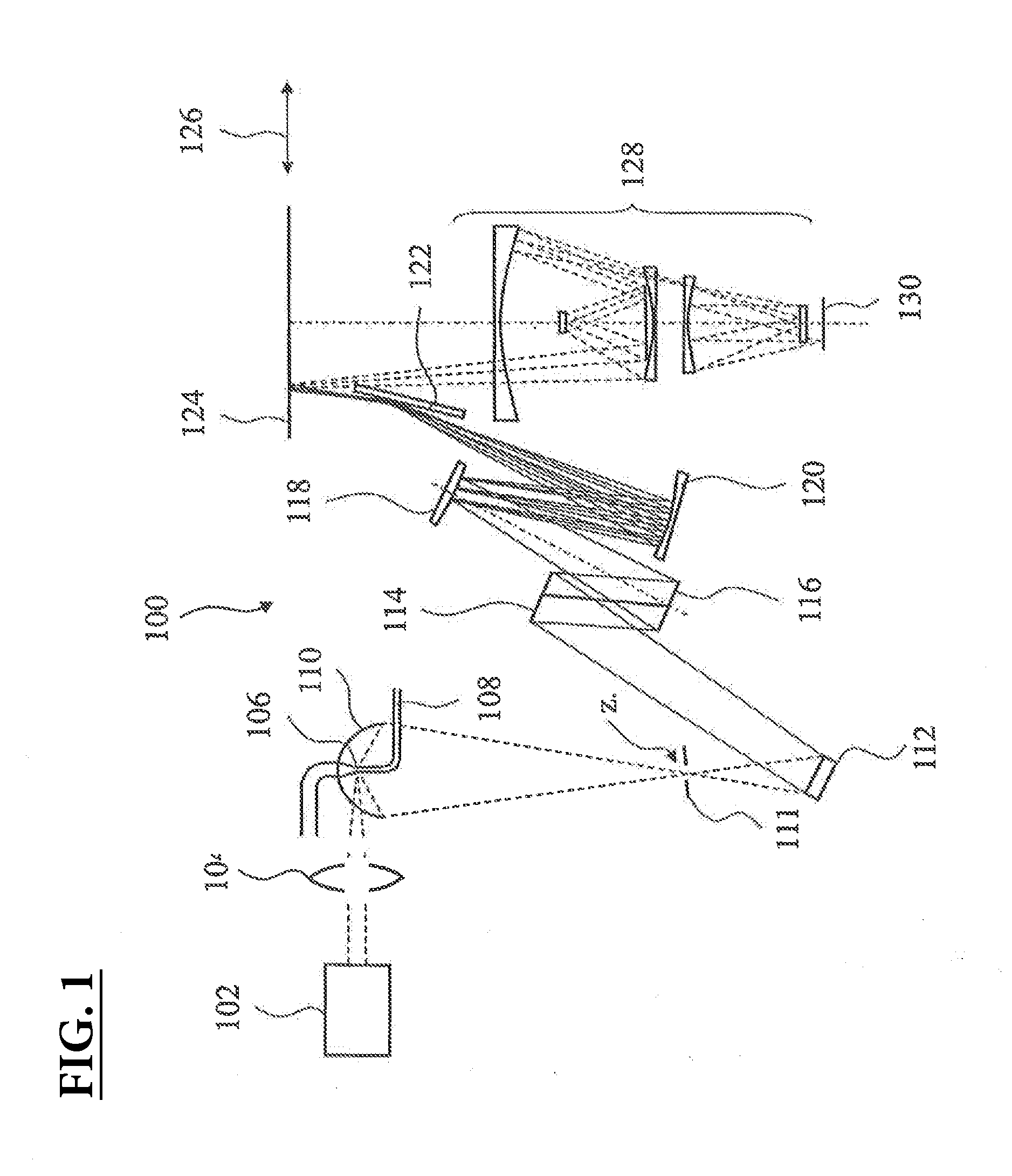
[0045]FIG. 1 shows a schematic view of a projection exposure apparatus 100 for producing microelectronic components, for example, which is operated in a scanning mode along a scanning direction 126 with an operating wavelength in the EUV range and which can have one or more optical elements having a layer arrangement. The projection exposure apparatus 100 shown in FIG. 1 has a virtually point-type plasma radiation source. The radiation from the laser source 102 is directed via a condenser lens element 104 onto suitable material which is introduced via the feed 108 and is excited to form plasma 106. The radiation emitted by the plasma 106 is imaged by the collector mirror 110 onto the intermediate focus Z. Corresponding stops 111 at the intermediate focus Z ensure that no undesirable stray radiation impinges on the downstream mirrors 112, 114, 116, 118, 120 of the illumination system of the projection exposure apparatus 100. The plane mirror 122 serves for folding the system, in orde...


PUM

PropertyMeasurementUnit
Fractionaaaaaaaaaa
Fractionaaaaaaaaaa
Fractionaaaaaaaaaa

Abstract

A mirror (1) for the EUV wavelength range having a reflectivity of greater than 40% for at least one angle of incidence of between 0° and 25° includes a substrate (S) and a layer arrangement, wherein the layer arrangement has at least one non-metallic individual layer (B, H, M), and wherein the non-metallic individual layer (B, H, M) has a doping with impurity atoms of between 10 ppb and 10%, in particular between 100 ppb and 0.1%, providing the non-metallic individual layer (B, H, M) with a charge carrier density of greater than 6*1010 cm−3 and/or an electrical conductivity of greater than 1*10−3 S/m, in particular with a charge carrier density of greater than 6*1013 cm−3 and/or an electrical conductivity of greater than 1 S/m.

Description

CROSS-REFERENCE TO RELATED APPLICATIONS[0001]This application is a Continuation Application of International Application No. PCT / EP2013 / 000663, filed on Mar. 6, 2013, which claims benefit under 35 U.S.C 119(e) of U.S. Provisional Application No. 61 / 608,229, filed Mar. 8, 2012, and which claims priority under 35 U.S.C. §119(a) to German Patent Application No. 10 2012 203 633.4, filed Mar. 8, 2012. The entire disclosures of all three related applications are considered part of and are incorporated by reference into the disclosure of the present application.FIELD OF AND BACKGROUND OF THE INVENTION[0002]The invention relates to a mirror for the EUV wavelength range and to a method for producing such a mirror. Furthermore, the invention relates to an EUV light source, an EUV illumination system and an EUV projection lens for microlithography comprising such a mirror. Moreover, the invention relates to a projection exposure apparatus for microlithography.[0003]Projection exposure apparatu...

Claims


Application Information

Patent Timeline
IPC IPC(8): G03F7/20C23C14/35C23C14/06G02B5/08
CPCG03F7/702C23C14/06C23C14/35G02B5/0891B82Y10/00G03F7/70316G21K1/062
Inventor HUBER, PETERVON BLANCKENHAGEN, GISELA
Owner CARL ZEISS SMT GMBH
Why Eureka
Try Eureka