Differential filtering chromatic confocal microscopic system

Active Publication Date: 2015-02-26
NAT TAIWAN UNIV
View PDF6 Cites 36 Cited by
  • Summary
  • Abstract
  • Description
  • Claims
  • Application Information

AI Technical Summary

Benefits of technology

[0014]The present invention provides a differential filtering chromatic confocal microscopic system, which modulates a broadband light into a point or linear broadband light for scanning the surface of the object so as to measure the surface profile of the object. By means of a optical intensity sensing module having a pair of light intensity sensing devices, a pair of spatial filters respectively corresponding to the pair of light intensity sensing devices and being arranged at the focal position of the two object lights, wherein the two spatial filters having different dimension from each other such as pinhole diameter or opening width of the slit, and a pair of color filters, each of which is arranged between each light intensity sensing device and corresponding spatial filter and allows a single color spectrum to pass therethrough, two differential rational values of optical intensity corresponding each object light are obtained whereby the problem of cross talk between different color spectrum can be reduced so as to increase accuracy of the surface inspection.

Problems solved by technology

Due to the large system volume inducing disadvantages of occupying too much space, various conventional systems are limited to perform surface profile measurement on the object, such as 8-inch wafer having a plurality of large scale integration (LSI) chips formed thereon when the volume or the surface inclined angle of the object is large, thereby reducing practicability and convenience of the entire configuration.
However, since the reflection rate with respect to RGB color of the inspection light is varied with the property of object surface, such as color of the object surface, it is necessary to establish a depth relation curve corresponding to the reflection rate of different colors for the surface profile measurement, which is inconvenient for the inspection operator.
In addition, another drawback is that the slit structure is indispensable for receiving the object light from the object in the convention configuration, so that a cross talk caused by an overlap between neighboring object lights, such as unfocused lights and stray lights, will be generated inevitably, thereby decreasing effect of image detection resolution.
In case of foregoing mentioned system having spatial filters that are arranged before and behind the focal position of the object lights, these conventional system for measuring the surface profile of the object are facing potential problems that are listed below:(1) Defocus issue: since the object lights are detected by the optical detectors arranged before and behind the focal position, the quality of the images generated from the optical detectors will be reduced thereby increasing the inaccuracy of the inspection.(2) Inaccuracy of image alignment: since the optical detectors are respectively arranged before and behind the focal position of the object light, the field of view (FOV) of the two optical detectors are different from each other thereby causing inspection inaccuracy.(3) Inconsistency of spatial resolution: since the optical detectors are respectively arranged before and behind the focal position of the object light, the field of view (FOV) of the two optical detectors are different from each other thereby causing inconsistency of spatial resolution.(4) Difficult to adjust position of optical detectors: when the chromatic dispersion objective is changed, the whole system should be calibrated especially the position of the two optical detectors, which will increase the inconveniency of the operation of the system.

Method used


Image

  • Differential filtering chromatic confocal microscopic system
  • Differential filtering chromatic confocal microscopic system
  • Differential filtering chromatic confocal microscopic system

Examples


first embodiment

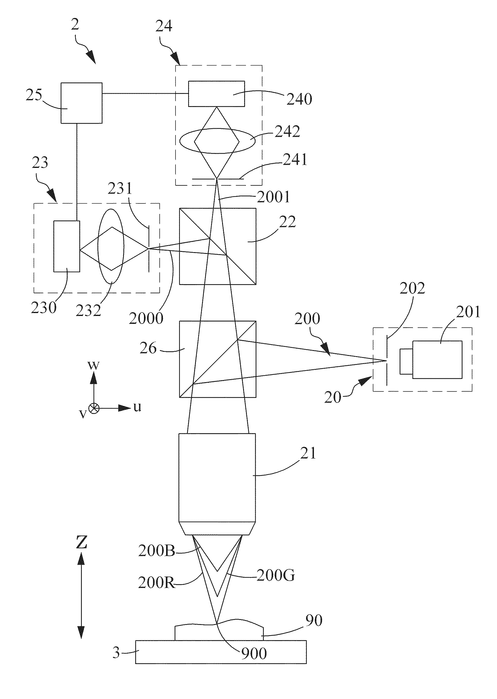
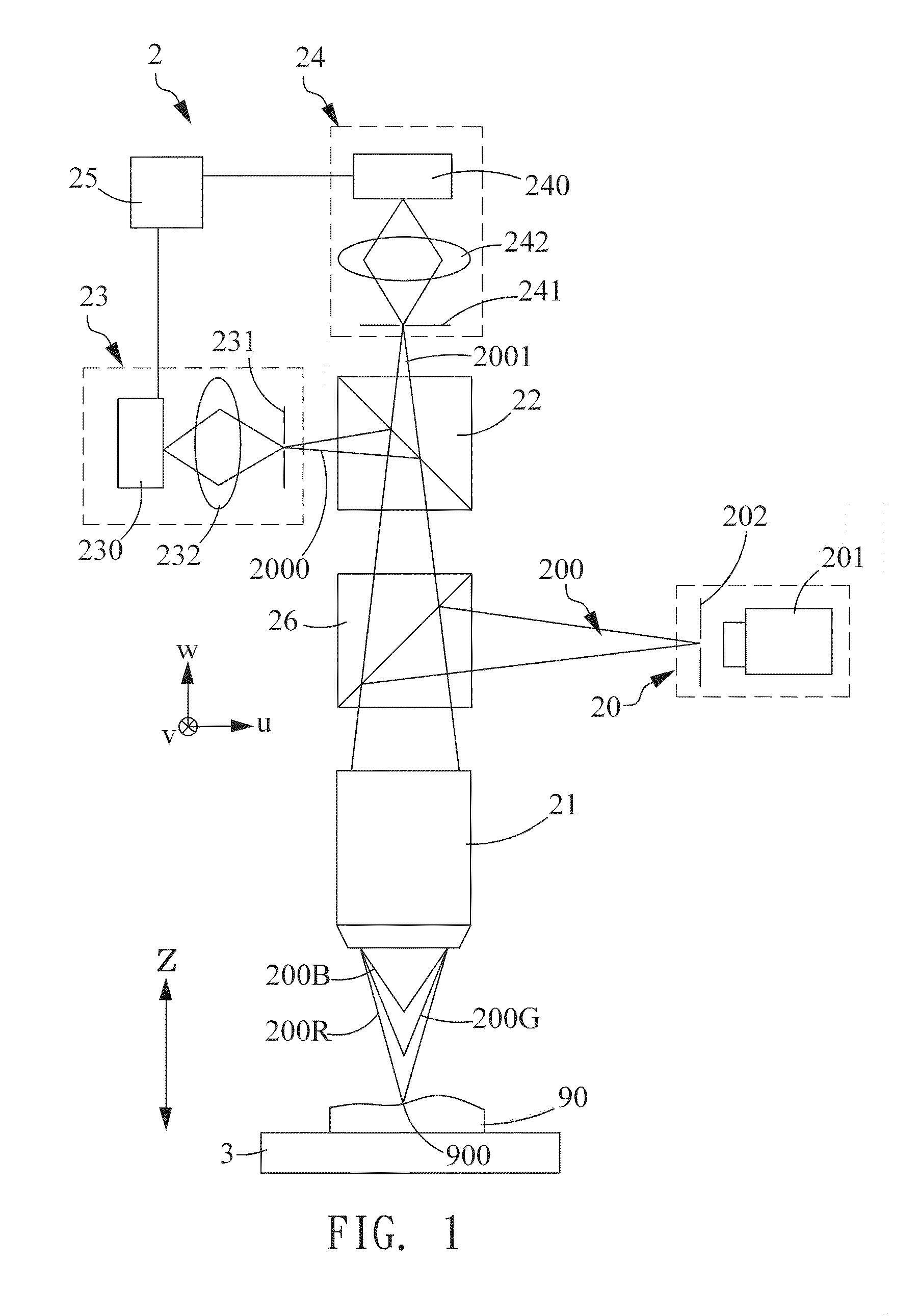
[0036]Please refer to FIG. 1 which illustrates a differential filtering chromatic confocal microscopic system according to the present invention. In the present embodiment, the differential filtering chromatic confocal microscopic system 2 comprises a light source module 20, a chromatic dispersion objective 21, a first optical modulation module 22, and a pair of first optical intensity sensing module 23 and 24, and a signal processing unit 25. The light source module 20 provides a broadband light 200, which can be, but should not limited to, single color light having a specific bandwidth such as red light (620 nm˜750 nm), green light (495 nm˜570 nm), or blue light (476˜495 nm). Alternatively, in another embodiment, the broadband light 200 can also be a composite light having a plurality of color spectrum, such as a white light having wavelength spectrum ranging from 380 nm to 750 nm. In the present embodiment, the broadband light is a white light.

[0037]In addition, the light source ...

second embodiment

[0063]Please refer to FIG. 6A, which illustrates a differential filtering chromatic confocal microscopic system according to the present invention. The confocal microscopic system 2a is basically similar to the system shown in FIG. 1, wherein the difference is that the light generated by the light source module 20 is a broadband light with a monochromatic spectrum such as red light spectrum 620 nm˜750 nm, green light spectrum 495 nm˜570 nm, or blue light spectrum 476 nm˜495 nm, each of which could be the broadband light emitted from the light source module 20.

[0064]In one embodiment, the light source module 20 comprises a color filter 203 such as red light filter, green light filter, or blue light filter, which allows a monochromatic spectrum passing therethrough. The color filter 203 is arranged between the shaping element 202, and the light generating device 201. When the white light generated from the light generating device 201 passes the color filter 203, a monochromatic broadb...

third embodiment

[0068]Please refer to FIG. 6B, which illustrates a differential filtering chromatic confocal microscopic system according to the present invention. In the present invention, the system 2b is basically similar to the system shown in FIG. 1, wherein the difference therebetween is that the first optical intensity sensing module 23 and 24 respectively comprise a monochromatic color filters 233 and 243 which are respectively arranged between the first light intensity sensing devices 230′ and 240′ and collecting elements 232 and 242. The monochromatic color filters 233 and 243 respectively filter the first and second object lights 2000 and 2001 so as to form two monochromatic object lights, respectively, wherein one of the monochromatic object light is detected by the first light intensity sensing device 230′ for generating a first optical intensity signal and the other monochromatic object light is detected by the second light intensity sensing device 240′ for generating a second optical...


PUM


Abstract

A differential filtering chromatic confocal microscopic system comprises a chromatic dispersion objective for receiving and axially dispersing a broadband light from a light source and projecting dispersed lights onto an object thereby forming an object light reflected therefrom; an optical modulation module for dividing the object light into a first and a second object lights; a pair of optical intensity sensing module, respectively having a spatial filter with a different pinhole diameter or a slit width from each other, for detecting the first and second object lights, thereby obtaining a plurality of first and second optical intensity signals; and a signal processor for respectively processing the plurality of first and second optical intensity signals thereby obtaining a plurality of differential rational values of optical intensity and determining a corresponding object depth associated with each differential rational value according to a relation between signal intensity ratio and object surface depth.

Description

FIELD OF THE INVENTION[0001]The present invention relates to a chromatic confocal measurement and more particularly, to a differential filtering chromatic confocal microscopic system for measuring a surface profile of an object according to two different optical intensities distribution corresponding to two spatial filters, respectively, wherein the two spatial filters have different dimension from each other and being disposed at focal position of the object light passing through the corresponding spatial filter.BACKGROUND OF THE INVENTION[0002]Conventional confocal chromatic microscope systems are installed on desktop so as to perform a vertical or lateral scan on an object for obtaining a surface profile thereof. Due to the large system volume inducing disadvantages of occupying too much space, various conventional systems are limited to perform surface profile measurement on the object, such as 8-inch wafer having a plurality of large scale integration (LSI) chips formed thereon...

Claims


Application Information

Patent Timeline
Patent Type & Authority Applications(United States)
IPC IPC(8): G02B21/06G02B21/00
CPCG02B21/0068G02B21/06G01B9/02036G01B9/02042G01B9/04G01N21/9501G01N2223/6116G01N2291/2697G02B21/0016G02B21/0032G02B21/006G02B21/0064G02B21/0072
Inventor CHEN, LIANG-CHIALIN, JIUN-DA
Owner NAT TAIWAN UNIV
Why Eureka
Try Eureka