Separation membrane manufacturing method

a technology of separation membrane and manufacturing method, which is applied in the field of separation membrane manufacturing method, can solve the problems of affecting the separation performance of the resulting separation membrane, affecting the separation performance of the membrane, and the membrane is deteriorated early, so as to achieve easy manufacturing, reduce drying, and facilitate manufacturing

Inactive Publication Date: 2015-02-26
NGK INSULATORS LTD
View PDF2 Cites 0 Cited by
  • Summary
  • Abstract
  • Description
  • Claims
  • Application Information

AI Technical Summary

Benefits of technology

[0020]According to the separation membrane manufacturing method of the present invention, a dense separation membrane can be easily manufactured. More specifically, in the separation membrane manufacturing method of the present invention, the ventilation drying in the drying step is performed as follows. That is, the temperature of a monolith substrate having a separation membrane precursor is raised to 90° C. within 15 minutes from the start of passing of hot air at such a rate of temperature rise that the average rate of temperature rise is 7° C./min or more from the start of the passing of the hot air until the temperature reaches 90° C. Such a structure enables easy manufacture of a dense separation membrane

Problems solved by technology

A zeolite membrane generally has poor resistance to acids, and thus the organic acids may lower separation performance of the membrane or cause early deterioration of the membrane.
In a separation membr

Method used


Image

  • Separation membrane manufacturing method
  • Separation membrane manufacturing method
  • Separation membrane manufacturing method

Examples


example 1

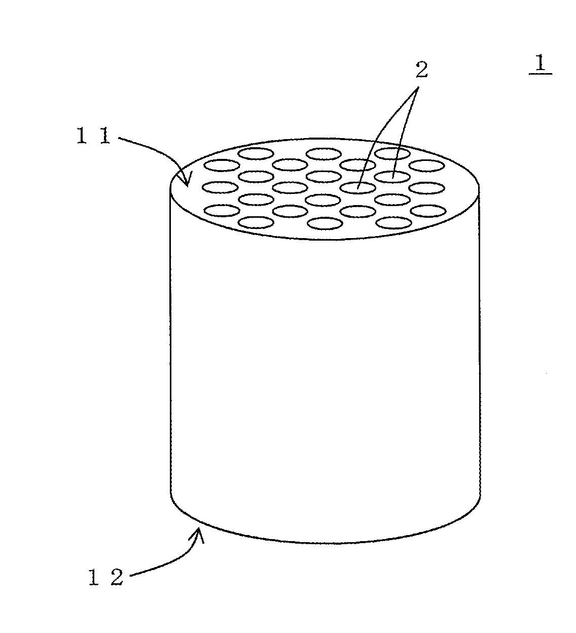
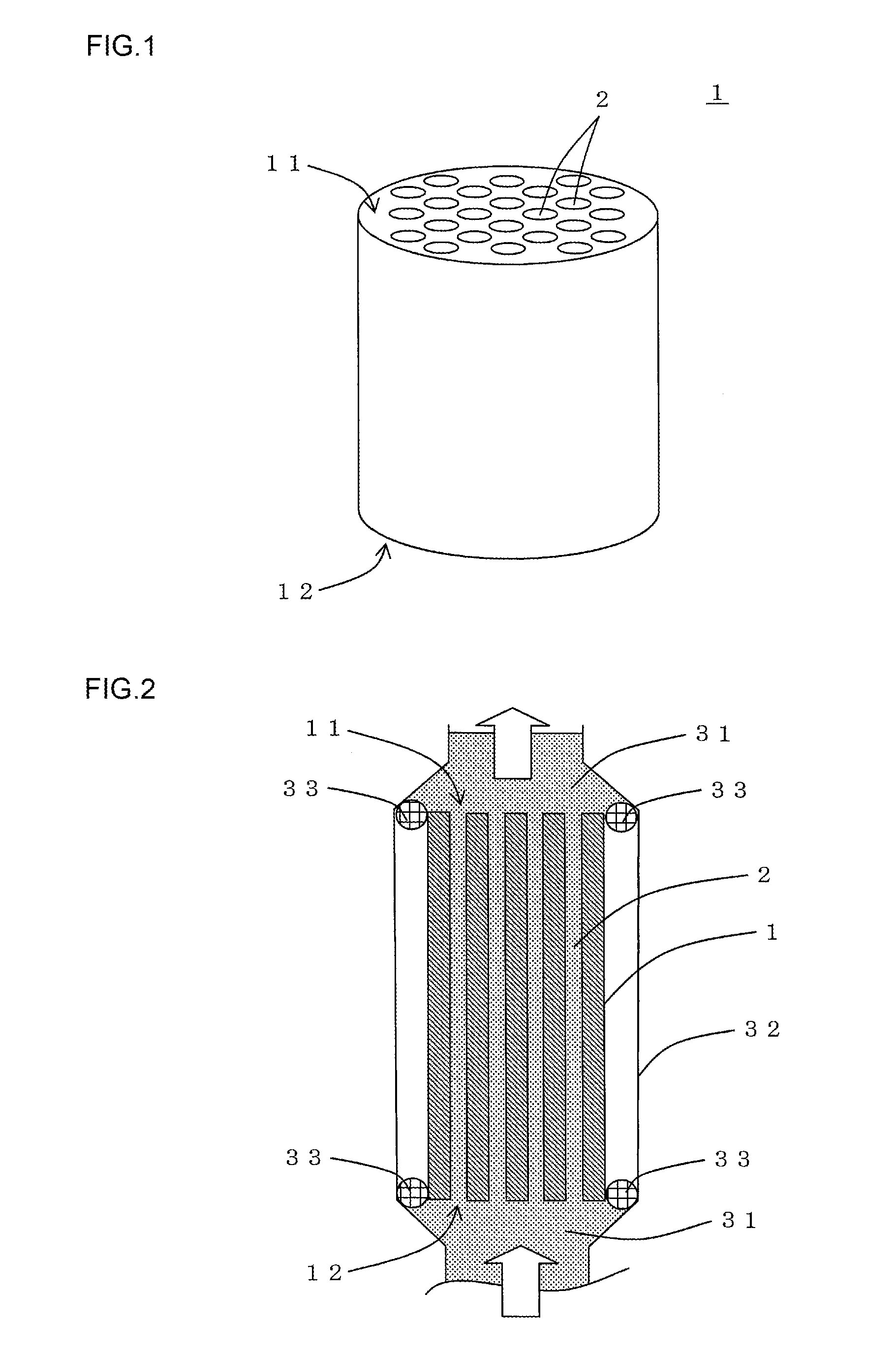
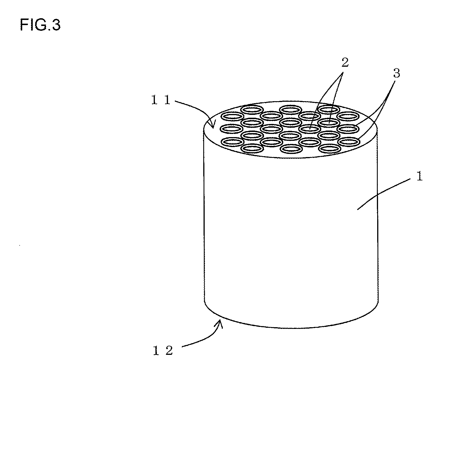
[0068]First, a porous monolith substrate was prepared as the substrate for manufacturing a separation membrane. The monolith substrate was made from alumina. The shape of the monolith substrate was a cylindrical shape having a first end face and a second end face. The diameter of the first end face and the second end face of the monolith substrate was 30 mm, and the length along the cell extending direction was 160 mm. In the monolith substrate, 55 cells extending from the first end face to the second end face were formed. The shape of the open ends of the cells was circular. The opening of a single cell had an area of 5 mm2.

[0069]Before the membrane forming step, a sealing tape was wound around the outer peripheral surface of the monolith substrate to prevent precursor solution from adhering to any area other than the surface of the cells in the monolith substrate.

[0070]Such a monolith substrate was disposed in a manner that the cell extending direction was in the vertical directio...

examples 2 and 3

[0079]In Examples 2 and 3, each separation membrane was manufactured by using a monolith substrate having the diameter and the length as shown in Table 1. In Example 2, during the ventilation drying in the drying step, hot air was sent in a manner that the average rate of temperature rise was 7° C. / min from the start of the passing of the hot air until the temperature reached 90° C. In Example 3, during the ventilation drying in the drying step, hot air was sent in a manner that the average rate of temperature rise was 10° C. / min from the start of the passing of the hot air until the temperature reached 90° C. The average rate of temperature rise (° C. / min) and the speed (m / s) of hot air are shown in Table 1. The shape of the monolith substrate used in Example 3 was a cylindrical shape having a first end face and a second end face, the diameter of the first end face and the second end face of the monolith substrate was 180 mm, and the length along the cell extending direction was 1,...


PUM

PropertyMeasurementUnit
Temperatureaaaaaaaaaa
Cooling rateaaaaaaaaaa

Abstract

Provided is a separation membrane manufacturing method capable of easily manufacturing a dense separation membrane. The separation membrane manufacturing method comprises a membrane forming step of forming a separation membrane precursor containing a separation membrane precursor solution on the surface of cells formed in a porous monolith substrate; and a drying step of performing ventilation drying by passing hot air through the cells having the separation membrane precursor in the monolith substrate to dry the separation membrane precursor. During the ventilation drying in the drying step, the temperature of the monolith substrate having the separation membrane precursor is raised to 90° C. within 15 minutes from the start of the passing of the hot air at such a rate of temperature rise that an average rate of temperature rise is 7° C./min or more from the start of the passing of the hot air until the temperature reaches 90° C.

Description

TECHNICAL FIELD[0001]The present invention relates to a separation membrane manufacturing method. More specifically, the present invention relates to a separation membrane manufacturing method capable of easily manufacturing a dense separation membrane.BACKGROUND ART[0002]In recent years, production of ethanol using biomass technology has drawn attention from the viewpoint of environmental protection and effective utilization of scrap wood. A method of using selective permeability of a zeolite membrane has been known as a method for recovering the ethanol produced by such biomass technology. The method comprises bringing a liquid mixture containing water and ethanol obtained from woody biomass into contact with the zeolite membrane to selectively pass water alone through the membrane, thus separating ethanol from water.[0003]The liquid mixture obtained from woody biomass contains organic acids such as acetic acid along with water and ethanol. A zeolite membrane generally has poor re...

Claims


Application Information

Patent Timeline
IPC IPC(8): B01D67/00B01D71/64
CPCB01D67/0044B01D67/0002B01D71/64B01D61/362B01D63/066B01D67/0067B01D71/021B01D2323/08
Inventor SAKAI, TETSUYASUZUKI, HIDEYUKIICHIKAWA, AKIMASAKINOSHITA, NAOTO
Owner NGK INSULATORS LTD
Why Eureka
Try Eureka