Precessional-motion bone and dental drilling tools and bone harvesting apparatus

Active Publication Date: 2015-02-26
SCIANAMBLO MICHAEL J
View PDF11 Cites 8 Cited by
  • Summary
  • Abstract
  • Description
  • Claims
  • Application Information

AI Technical Summary

Benefits of technology

[0031]Particular embodiments of the subject matter described in this document can be implemented to realize one or more of the following advantages. In some embodiments, the orthopedic drilling instruments described herein can provide more efficient osteotomy procedures, and osteotomy procedures which are safer for a patient. An instrument that is both flexible and strong resists breaking and injuring the patient. An instrument that is flexible and has a center of mass offset from an axis of rotation may swing out from the axis of rotation as the instrument is rotated at high speeds, such as when the instrument is used with a motorized actuator tool. If the instrument is configured to bend an equal amount at each angle of rotation, the inner diameter of a space can be contacted by the instrument and uniformly cleaned. The

Problems solved by technology

In addition to the minimal improvements in drill technology, these designs offer little opportunity to collect bone for an autograft, which is often necessary.
Harvesting autologous bone from a donor site results in additional time and the attendant risk of complications such as donor site pain and morbidity.
Allografts, derived from donor (cadaver) tissues, are only osteo-conductive, and may pose the risk of contamination.
Artificial materials such as alloplastic bone cement are a poor choice for grafting since they are potentially antigenic and rarely osteo-conductive.
Performing osteotomies can be challenging even with optimal illumination, magnification and good assistance.
Fo

Method used


Image

  • Precessional-motion bone and dental drilling tools and bone harvesting apparatus
  • Precessional-motion bone and dental drilling tools and bone harvesting apparatus
  • Precessional-motion bone and dental drilling tools and bone harvesting apparatus

Examples


Embodiment Construction

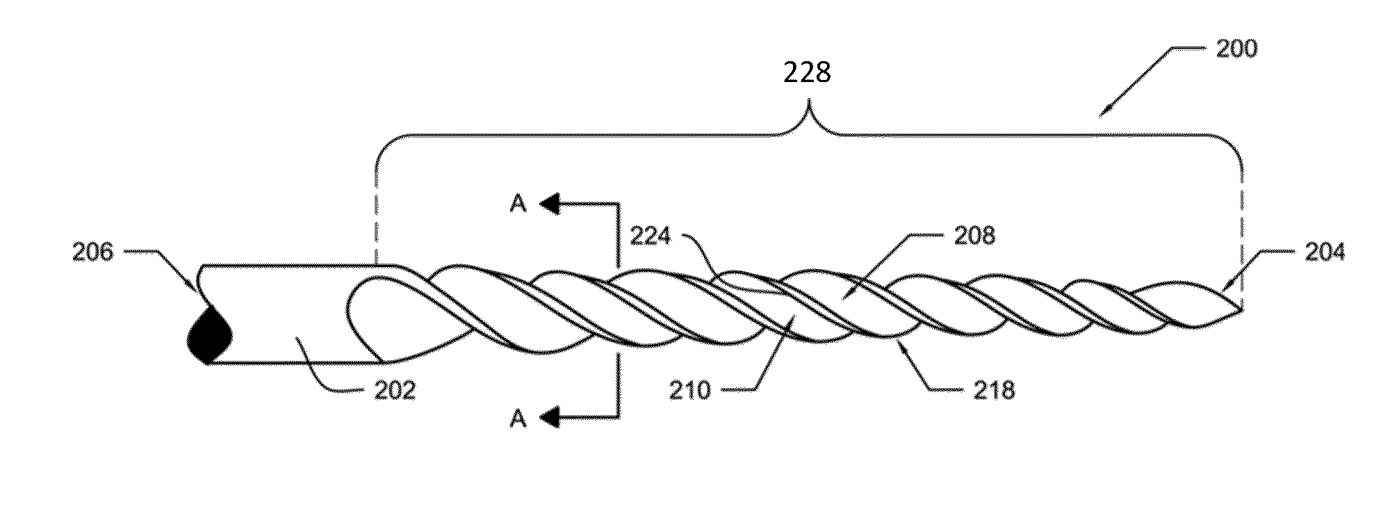
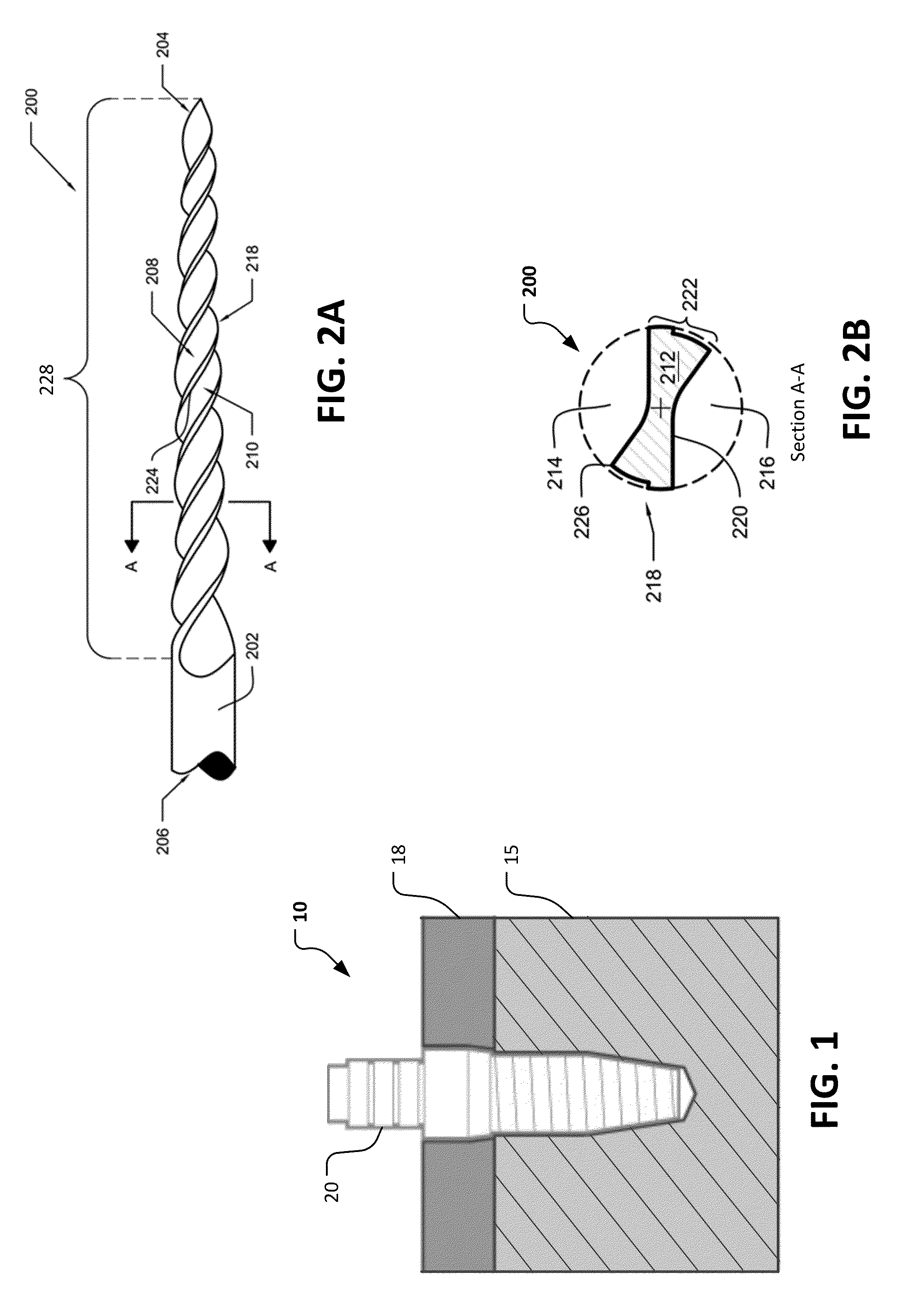
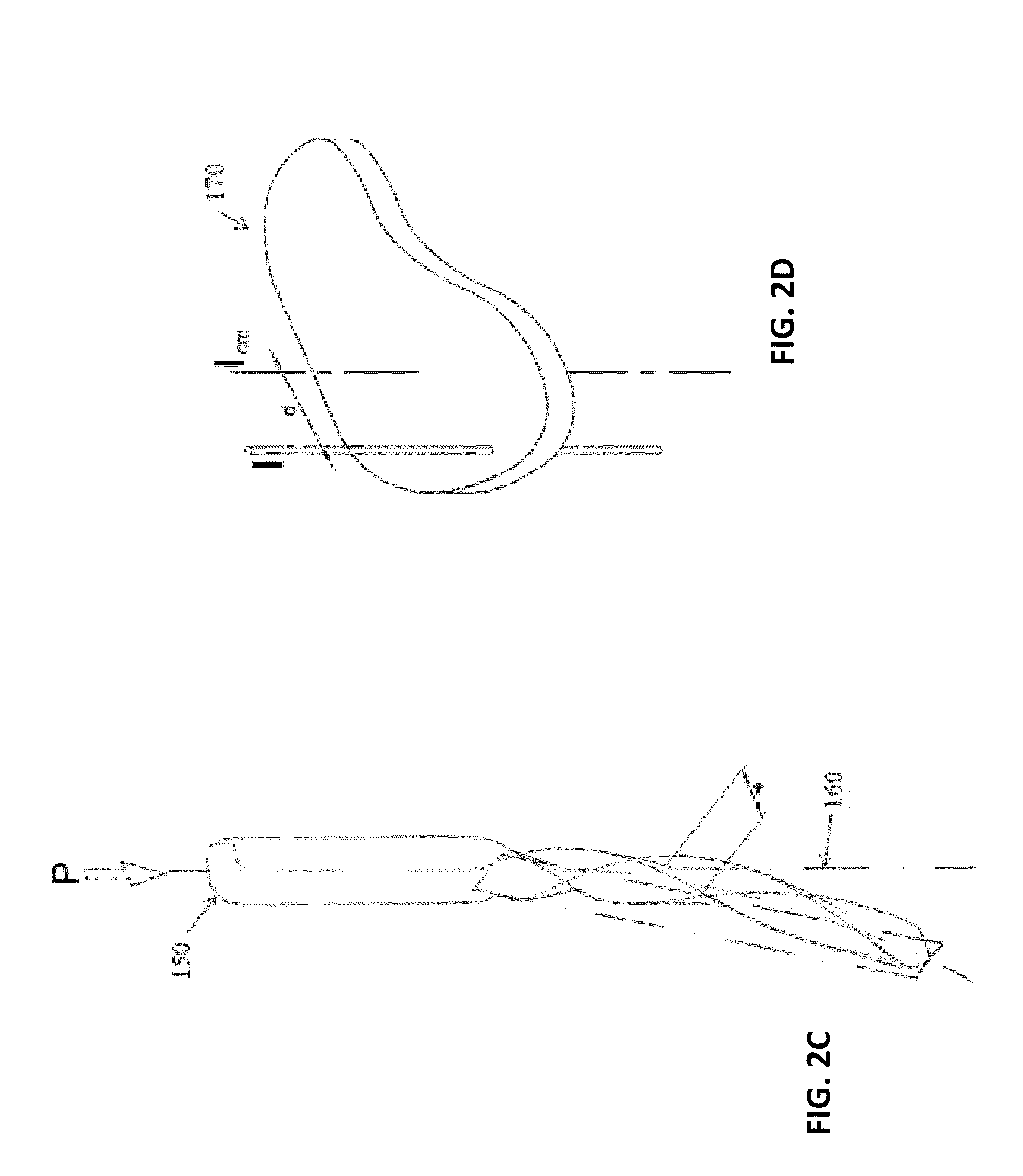
[0069]In a first context, this document provides orthopedic devices and methods for their use. For example, novel bone drills for preparing an osteotomy are provided. The drilling instruments provided herein have at least some cross-sections (perpendicular to the axis of rotation) with centers of mass that are offset from the drills' axis of rotation. The offset center of mass may allow the drills to generate precessional motion or form mechanical waves when in use. In a second context, this document provides precessional-motion drilling tools for industrial use. For example, this document provides drill bits and methods of use for drilling a variety of materials including, but not limited to, metals, ceramics, wood, plasterboard, plastics, stone, composites, synthetics, silicon, and the like.

[0070]A great deal of mathematics and engineering has been dedicated to modeling, studying and solving the problems associated with high frequency and low frequency vibrations during drilling i...


PUM

PropertyMeasurementUnit
Angleaaaaaaaaaa
Diameteraaaaaaaaaa
Diameteraaaaaaaaaa

Abstract

This document provides orthopedic and dental devices and methods for their use. For example, novel bone drills and dental drills are described. The bone and dental drills have at least some centers of mass that are offset from the drills' axis of rotation. Accordingly, the bone and dental drills may rotate and cut using a precessional pattern of motion. The design facilitates bone cutting, chip formation and hauling capacity, irrigation and bone harvesting. In some embodiments, the bone chips are collected in a removable apparatus fixed to the distal portion of the drill, and the collected bone chips can be used for bone grafting.

Description

CROSS-REFERENCE TO RELATED APPLICATIONS[0001]This application claims priority to U.S. Provisional Application No. 61 / 868,276, filed Aug. 21, 2013, and U.S. Provisional Application No. 61 / 899,705, filed Nov. 4, 2013. The disclosures of the prior applications are considered part of (and are incorporated by reference in) the disclosure of this application.BACKGROUND[0002]1. Technical Field[0003]In a first context, this document relates to orthopedic devices and methods for their use. For example, this document relates to novel bone drills for performing osteotomies or for drilling holes in bones. The bone drills have at least some centers of mass that are offset from the drill's axis of rotation. Accordingly, the bone drills may rotate and cut using a precessional pattern of motion. In a second context, this document relates to precessional-motion drilling tools generally. For example, this document relates to drill bits and methods of use for drilling a variety of materials including,...

Claims


Application Information

Patent Timeline
IPC IPC(8): A61B17/16A61C3/02
CPCA61B17/1615A61B17/164A61C3/02B23B51/00B28D1/14B23B2250/16B23B2251/204B23B2251/245B28D1/146B23B51/0081B23B2251/244Y10T408/89Y10T408/905Y10T408/909Y10T408/9097Y10T409/303808Y10T408/03Y10T408/455B23B51/02A61B17/1635
Inventor SCIANAMBLO, MICHAEL J.
Owner SCIANAMBLO MICHAEL J
Why Eureka
Try Eureka