Electrophilic acid gas-reactive fluid, proppant, and process for enhanced fracturing and recovery of energy producing materials

Active Publication Date: 2015-03-05
BATTELLE MEMORIAL INST
View PDF7 Cites 2 Cited by
  • Summary
  • Abstract
  • Description
  • Claims
  • Application Information

AI Technical Summary

Benefits of technology

The present invention provides a new electrophilic acid gas reactive fracturing and recovery fluid for enhanced fracturing and recovery of energy-producing materials from subterranean bedrock and shale rock. The fluid includes an electrophilic acid gas-reactive compound in an aqueous or organic solvent, or a combination of both, which can chemically expand in the reservoir to create a pressure that propagates fractures in the bedrock. The fluid also includes a proppant, such as solid particles, that can hold the fractures open and enhance the recovery of energy-producing materials. The process of fracturing and recovery using this new fluid results in improved energy production.

Problems solved by technology
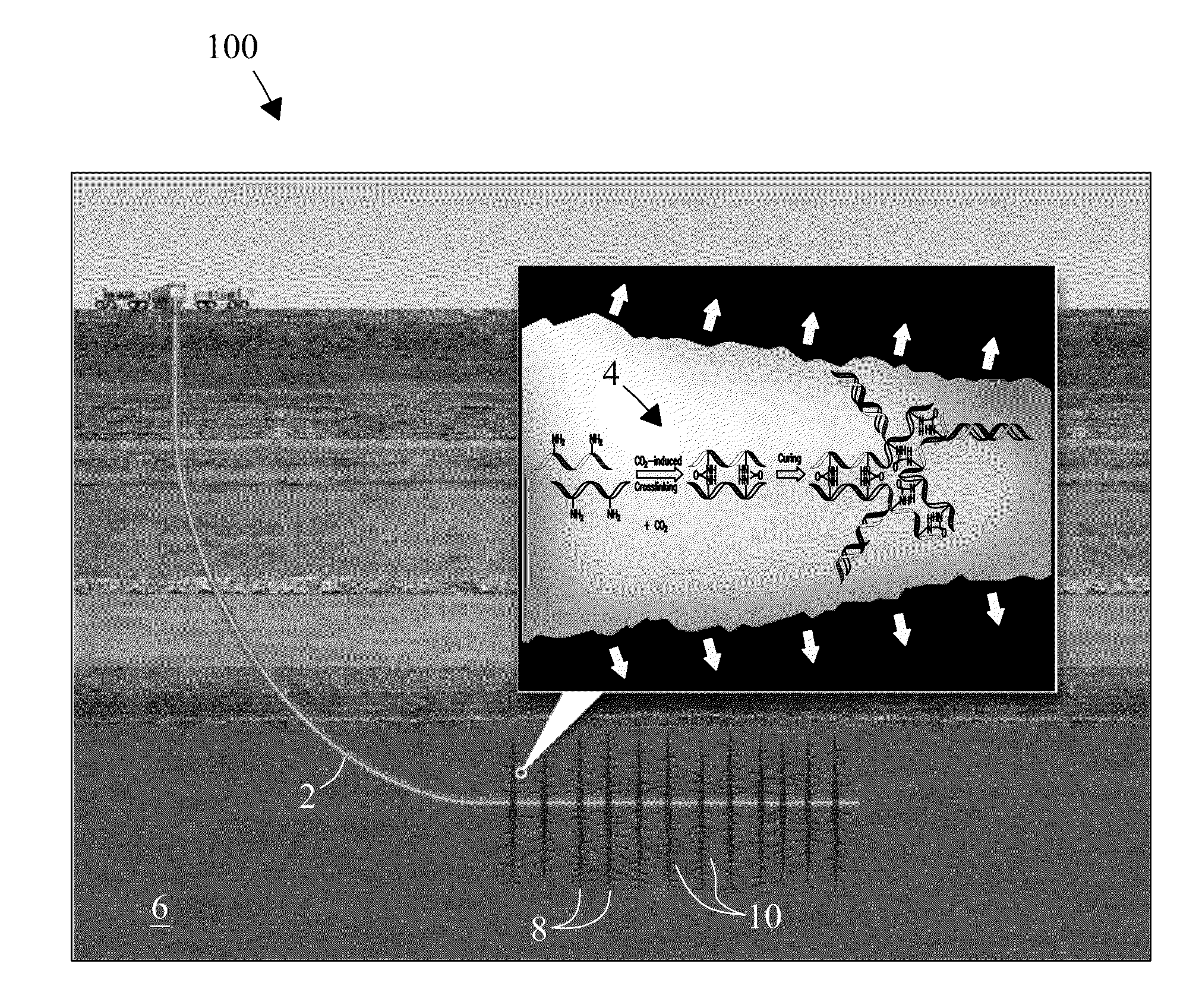
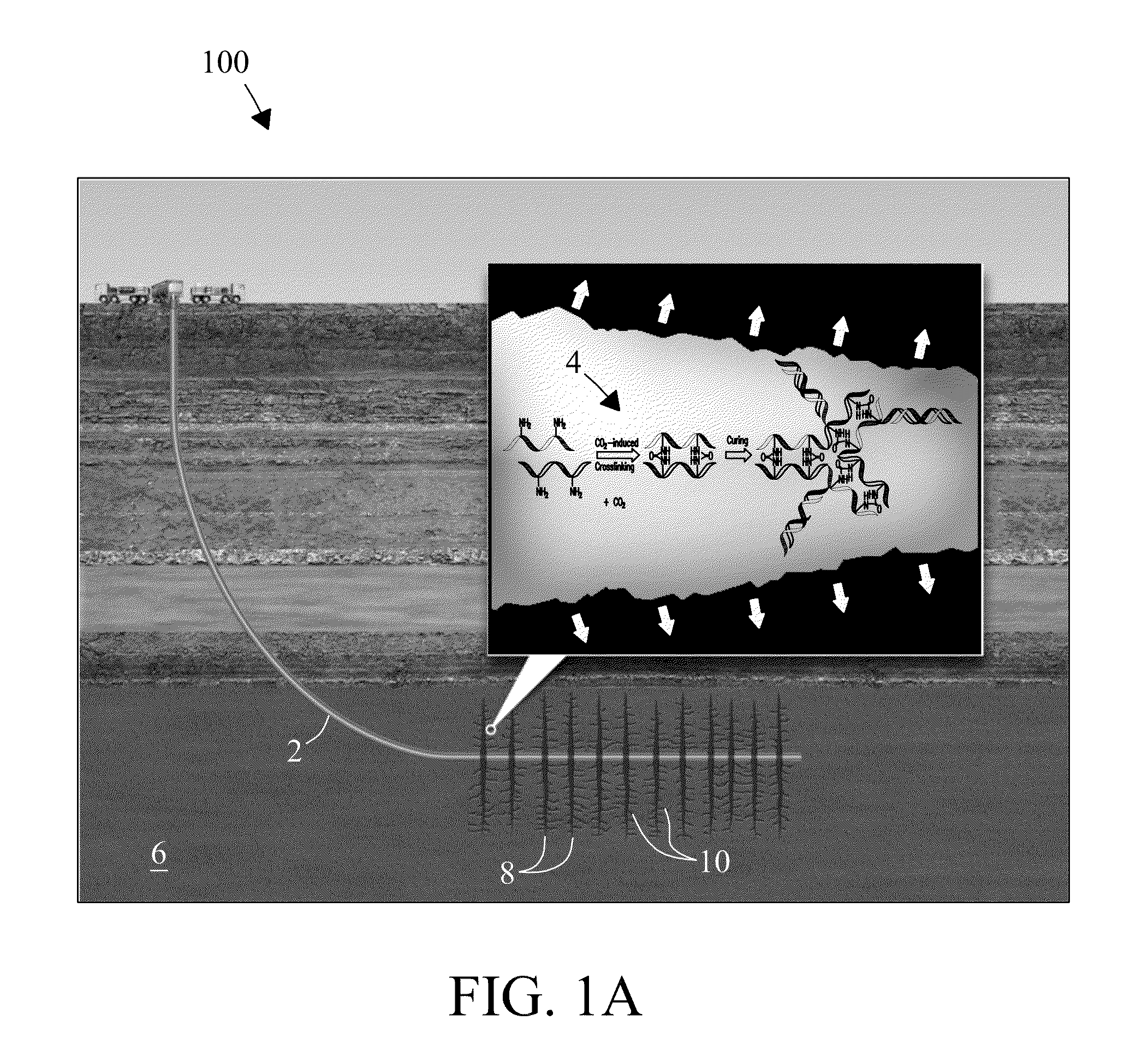
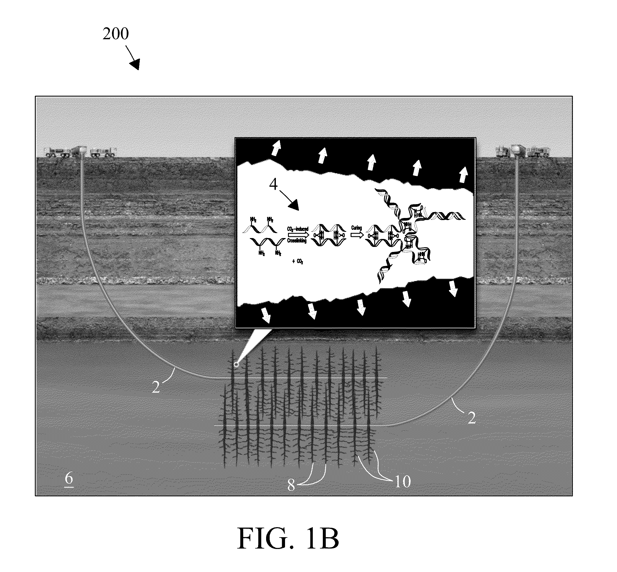
However, recovering energy-producing materials from subterranean bedrock or shale rock beneath the earth's surface is not easily achieved currently or in a cost-effective or efficient manner due to a lack of permeability in the native bedrock at depths, e.g., between about 3 km to about 10 km.
However, to date, EGS systems have yet to attain sustainable flow rates, production rates, and / or yields needed for economic viability.
However, well-known problems exist with conventional fracking fluids.
Dense and heavy proppants when introduced can cause excessive loads on injection pumps and increase costs for pumping.
In addition, chemicals introduced in fracturing fluids can leach into aquifers and contaminate the ground water or deleteriously impact the environment where reservoirs are located.
Others can be carcinogenic or can include explosives or other high-energy compounds that themselves are problematic or otherwise require extreme or careful handling.
Further, fracturing fluids developed for oil / gas recovery may not be applicable for geothermal recovery due to the fact that temperatures greater than 150° C. can degrade process chemicals.
Finally, injected chemical additives and drilling mud can also be physically difficult to remove from the bedrock formation once a new fracture front is formed resulting in decreased flow rates and decreased heat transfer.

Method used


Image

  • Electrophilic acid gas-reactive fluid, proppant, and process for enhanced fracturing and recovery of energy producing materials
  • Electrophilic acid gas-reactive fluid, proppant, and process for enhanced fracturing and recovery of energy producing materials
  • Electrophilic acid gas-reactive fluid, proppant, and process for enhanced fracturing and recovery of energy producing materials

Examples


example 1

Rheological Properties of PAA

[0064]Rheological properties of a 1 wt % polyallylamine (PAA) solution, 0.1% xanthan gum solution, and 1 wt % SDS (sodium dodecyl sulfate) solution were measured in a rheometer (e.g., a Physica MCR101 rheometer, Anton PAAR, Ashland, Va., USA) equipped with a temperature control system (e.g., a model C-PTD200, Peltier, Ashland, Va., USA) and a high-pressure reaction cell (e.g., CC25 / PR150, Ashland, Va., USA) (maximum temperature and pressure limits: 200° C. and 2000 psi) at a CO2 pressure of 2000 psi (136 atm) (1.38E+04 kPa) and a temperature of 190° C. For the rheology measurement, the pressure cell (vol.=26 mL) was first preheated to 90° C. Water or a chemical solution (13 mL) was then introduced into the cell through a port and heated to a final temperature of 190° C. CO2 was then introduced into the cell with an infusion pump (e.g., ISCO pump, Lincoln, Nebr. USA) in steps of about 100 psi (6.89 E+02 kPa) until the desired pressure was reached. Viscosi...

example 2

NMR Analyses of PAA

[0065]Polyallylamine (Gelest Inc., Morrisville, Pa., USA) was prepared as a 1 wt % solution in deionized water and introduced into a High Pressure Magic Angle Spinning rotor (HP MAS rotors) as an exemplary gas-reactive compound for 13C NMR chemical analysis. A rotor with a 7.5 mm O.D. and a 6.0 mm I.D. with a sample capacity of 450 μL was used equipped with a valve that allowed controlled exposure of an exemplary fracturing fluid of the present invention to pressurized gas. A 200 uL sample of a 1 wt % PAA solution was loaded into the rotor for scCO2 exposure at 72° C. and 86.2 bar (1250 psi) (8.62E+03 kPa). NMR spectra were collected in situ at temperatures over the range from 72° C. to 154° C. regulated within a temperature controlled oven (±0.1° C.) (e.g., a DC-256 oven, Thermal Product Solutions, White Deer, Pa., USA) monitored by two thermocouples within the HP-MAS rotor reaction chamber. Pressures (±1 psi or ±6.89 kPa) were measured with transducers from a du...

example 3

Effect of Temperature on Rheology of Expansion Polymer

[0068]Additional experiments on the reaction between PAA (polyallylamine) solution and CO2 were conducted at internal temperatures ranging from approximately 60° C. to 400° C. and pressures between about 110 atm and about 300 atm to understand the effect of temperature on the rheology of the PAA solution during the reaction with CO2. The high pressure cell was filled with 1 wt % PAA solution up to ˜40-50% level in the window before introducing CO2 at a range of external temperatures of 50° C., 100° C., 150° C., 200° C., 250° C., and 300° C., which correspond to the internal temperature of 58° C., 127° C., 196° C., 265° C., 333° C., and 402° C. based on the external and internal temperature calibration curve. Prior to CO2 injection, internal pressure of the high pressure cell containing PAA solution was ˜1 atm (1.01E+02 kPa) due to the presence of air and some water vapor at temperatures of 58° C.-196° C., and approximately 40 atm...


PUM

PropertyMeasurementUnit
Temperatureaaaaaaaaaa
Fractionaaaaaaaaaa
Fractionaaaaaaaaaa

Abstract

An electrophilic acid gas-reactive fracturing and recovery fluid, proppant, and process are detailed. The fluid expands in volume to provide rapid and controlled increases in pressure that enhances fracturing in subterranean bedrock for recovery of energy-producing materials. Proppants stabilize openings in fractures and fissures following fracturing.

Description

CROSS REFERENCE TO RELATED APPLICATION[0001]This is a non-provisional application that claims priority from U.S. Provisional Application No. 61 / 873,646 filed 4 Sep. 2013, which reference is incorporated in its entirety herein.STATEMENT REGARDING RIGHTS TO INVENTION MADE UNDER FEDERALLY-SPONSORED RESEARCH AND DEVELOPMENT[0002]This invention was made with Government support under Contract DE-AC05-76RLO-1830 awarded by the U.S. Department of Energy. The Government has certain rights in the invention.FIELD OF THE INVENTION[0003]The present invention relates generally to fracturing systems and processes. More particularly, the present invention relates to an electrophilic acid gas reactive fracturing fluid, proppant, and process that provide enhanced fracturing and recovery of energy producing materials from subterranean reservoirs.BACKGROUND OF THE INVENTION[0004]The urgent need for energy from cost-effective renewable energy sources is well recognized. Enhanced Geothermal Systems (EGS)...

Claims


Application Information

Patent Timeline
IPC IPC(8): C09K8/594E21B43/26C09K8/80E21B43/267C09K8/68
CPCC09K8/594E21B43/267E21B43/26C09K8/805C09K8/68Y10T428/2982E21B43/2605
Inventor FERNANDEZ, CARLOS A.HELDEBRANT, DAVID J.BONNEVILLE, ALAIN H. R.JUNG, HUN BOKCARROLL, KENNETH C.
Owner BATTELLE MEMORIAL INST
Why Eureka
Try Eureka