Wearable tactile display

a tactile display and wearable technology, applied in the field of tactile display devices, can solve the problems of difficult miniaturization, difficult embedding, and achieving close spacing, and achieve the effects of realistic perception and feeling, easy movement, and easy transportation

Active Publication Date: 2015-03-05
NAIDU PRAKASH C R J +1
View PDF10 Cites 26 Cited by
  • Summary
  • Abstract
  • Description
  • Claims
  • Application Information

AI Technical Summary

Benefits of technology

[0012]According to one specific application of the invention, the wearable tactile display is attached to a blind person's human finger such that an array of pins is in contact with the finger. The mouse type block of wearable tactile display may be moved easily over a Tablet type surface to enable tactile reading of the information to be conveyed depending on the location of the block on the Tablet. The vibratory actuation pattern of the pins can then convey the information otherwise conveyed by physical protrusion by means such as ridges of an embossed paper normally used in such tablets while a related audio commentary is provided through a computer attached to the tablet. This enables software based programming of information such as maps for education and navigation needs of blind individuals, substituting embossed paper based means that are inflexible, difficult to transport, and expensive.
[0013]According to another specific application, the single point force feedback capability of haptic devices such as Phantom® can be augmented by multi-point wearable tactile display attached on the thimble of haptic devices enabling realistic perception and feeling of 3D models of virtual objects in computer. Many other applications in the fields of Human-Machine Interfaces are also possible; for example: (a) Mobility and Education Aid for people who are visually impaired or blind; (b) Better and easier interaction at Kiosks; (c) Improved and novel infotainment systems interfaces; (d) Improved video gaming experience for mobile, residential stand-alone, residential online, and arcade gaming at Family Entertainment Centers (FECs); (e) Improved and varied communication through mobile devices such as mobile phones; (f) Improved haptic manipulation enhanced with tactile displays embedded in current haptic devices.

Problems solved by technology

The motor driven actuators based array systems suffer from constraints in miniaturization due to minimum size of motor and actuator elements that makes it difficult to embed them on a wearable substrate with the desirable flexibility and space resolution.
The pressurized fluid actuators based system requires a complex grid of valves for control of actuation, again imposing difficulty in miniaturization, embedding, and achievement of close spacing.
Other type of piezoelectric actuators, such as for example screw type actuators (Henderson, U.S. Pat. Nos. 6,940,209; 7,170,214; 7,309, 943; 7,339,306) appear to be having limitations in terms of frequency of vibration, tend to get stuck at the ends of the stroke of the actuator, and additionally occupy lateral space due to required screw and nut components limiting center-to-center distance between the pins vibrating for tactile stimulation (the minimum housing nut cross section dimension currently is 2.8 mm square resulting in minimum possible center-to-center distance between adjacent pins to be about 3 mm).
An alternative approach adopted by Kyung et al and Kim et al using disc based actuators called Tiny Ultrasonic Linear Actuator (TULA) that replaces screw by friction between disc hole and rod also has limitations in minimum center-to-center distance between adjacent pins that can be achieved because the actuators use piezoelectric bimorph discs that are 4 mm diameter and rods that pass through the center holes through discs are 1 mm diameter.
Moreover, these actuators need very high frequency generation circuit (for example, TULA-35 manufactured by Piezoelectric Technology, Seoul, S. Korea operates at 128 kHz frequency) and are primarily intended for displacement actuation as a friction based actuation substitute for screw based positioning, and as such do not appear to be ideally suitable for vibratory stimulation of human body parts with desired parameters of as close as possible to 1 mm spatial resolution and 50 Hz-500 Hz temporal resolution.
Our study and analysis has revealed that although piezoelectric actuation approach has been used in Braille displays so far, the current configurations are suitable for certain applications such as identification of a contact with a surface, for example, with a push button or pin and subsequent relative sliding motion between the contact and the surface to identify an adjacent button or pin that may be 3 mm or more distance apart; but they have many limitations that are restricting progress towards the type of configuration needed for wearable tactile display.

Method used


Image

  • Wearable tactile display
  • Wearable tactile display
  • Wearable tactile display

Examples


Embodiment Construction

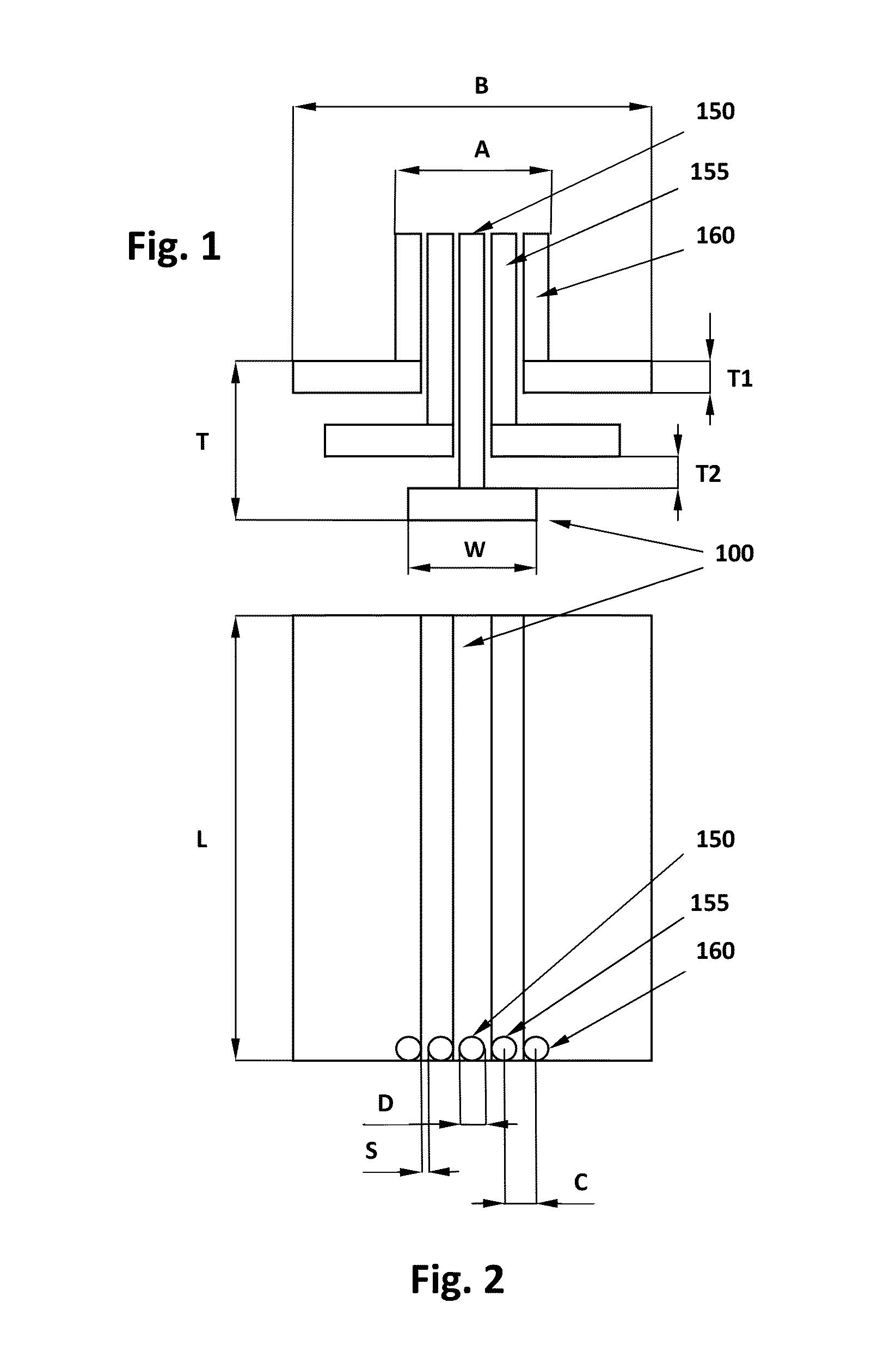
[0026]An embodiment of the invention is illustrated in FIG. 1 wherein a piezoelectric element 100 is placed at the bottom of a stack of similar overlapping piezoelectric elements arranged at different planes one over another. The piezoelectric element used in the embodiment is W wide measuring 3.2 mm (0.125 inch), has thickness T1 measuring 0.51 mm (0.02 inch), and length L measuring 31.8 mm (1.25 inch) and is manufactured by Piezo Systems Inc, Woburn, Mass. Other sizes and / or makes may be used. The Figure is a front elevation view as seen from the end side of the stack where the cantilever piezoelectric elements are free to move in vibratory motion in a direction up and down normal to the planes in which the elements are laying. In the illustrated configuration, one piezoelectric element is at the bottom of the stack with a vibratory stimulation pin 150 placed very close to the tip of the element as can be seen in the top view of the arrangement depicted in FIG. 2. The pin shown is...


PUM


Abstract

A wearable tactile display device is disclosed wherein vibrating stimulation pins are located close to each other by means of underlying vibratory actuation piezoelectric bending elements arranged in a cantilever configuration partially overlapping over each other. Optionally, the plane in which the tips of stimulation pins protrude may be a curved surface providing with the ability to comply with a curved human body part such as a finger. Vibratory stimulation can be achieved at close spatial resolution by advantageously reducing the space between adjacent stimulation pins through their ability to engage with different adjacent piezoelectric cantilever bending elements when they are placed at different planes and at additional closer spatial resolution when they are placed at an angle to each other. The programmable controller employed in order to program the pattern of stimulation pin vibrations can be used for generating different amplitudes and frequencies of vibration.

Description

RELATED U.S. PROVISIONAL PATENT APPLICATION[0001]This application claims the benefit of U.S. Provisional Patent Application No. 61 / 693,507, filed 27 August, 2012, including all the written description of the inventions described therein and making claim to the inventions disclosed therein.STATEMENT REGARDING FEDERALLY SPONSORED RESEARCH OR DEVELOPMENT[0002]The work on which the disclosure of this application is based is partially funded by National Science Foundation (NSF) under the Small Business Innovation Research (SBIR) program.BACKGROUND OF THE INVENTION[0003]This invention relates to tactile display device enabling tactile stimulation through vibration in human-machine interfaces such as communication of information to blind individuals and other touch based interfaces in equipments such as kiosks, mobile phones, and computer based gaming devices. Some aspects of the invention are applicable to an implementation of the invention integrating tactile display device with equipmen...

Claims


Application Information

Patent Timeline
Patent Type & Authority Applications(United States)
IPC IPC(8): G06F3/041
CPCG06F3/041G06F1/163G06F3/016
Inventor NAIDU, PRAKASHMANDAYAM, SRINIVASAN A.
Owner NAIDU PRAKASH C R J
Why Eureka
Try Eureka