
High-voltage and high-capacitance activated carbon and carbon-based electrodes

Active Publication Date: 2015-03-05
CORNING INC
View PDF20 Cites 13 Cited by
  • Summary
  • Abstract
  • Description
  • Claims
  • Application Information

AI Technical Summary

Benefits of technology

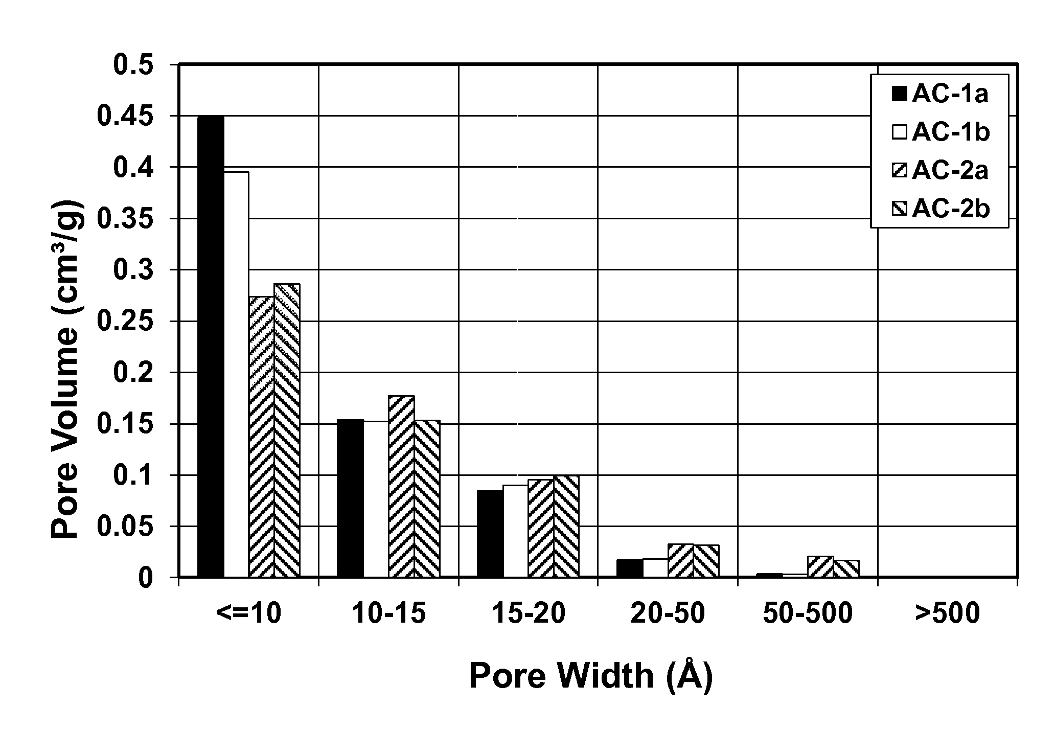
The patent discusses how to improve the performance of energy storage devices called EDLCs by using carbon-based electrodes with high voltage stability. By controlling the pore size distribution and oxygen content of the activated carbon, researchers hope to minimize unwanted reactions and achieve higher energy and power densities in the next generation of EDLCs.

Problems solved by technology

Such reactions can degrade the performance of a device comprising the activated carbon.

Method used


Image

  • High-voltage and high-capacitance activated carbon and carbon-based electrodes
  • High-voltage and high-capacitance activated carbon and carbon-based electrodes
  • High-voltage and high-capacitance activated carbon and carbon-based electrodes

Examples


example 1

[0059]Wheat flour (8000 g) is placed in a graphite crucible and heated in a retort furnace (CM Furnaces model 1216FL). The furnace temperature is increased at a heating rate of 150° C. / hr from room temperature to 800° C., maintained at 800° C. for 2 hrs, and then allowed to cool down naturally to 70° C. or less. During the foregoing heating / cooling cycle, the furnace is purged with N2.

[0060]As a result of heating under flowing N2, the wheat flour is carbonized and converted to a carbon material. The carbon can be ground to a powder using a hammer pound, pulverization and vibramilling. The ground carbon powder can have a particle size (d50) of 10 micrometers or less (e.g., 1, 2, 5 or 10 micrometers).

[0061]The powdered carbon (550 grams) is mixed with 1210 grams of KOH powder. The carbon / KOH mixture is placed in SiC crucibles (Hexoloy® SA grade) and heated in a retort furnace. The furnace temperature is increased at a heating rate of 150° C. / hr from room temperature to 750° C., mainta...

example 2

[0067]A commercially-available steam-activated carbon derived from coconut shells was used to prepare a second activated carbon material.

[0068]In one embodiment, the steam-activated carbon was used as received and designated as Sample AC-2a. In another embodiment, the steam-activated carbon was washed and filtered in dilute HCl and DI water until pH neutral, followed by heat treatment under 1% H2 / N2 purge at 900° C. (similar to Sample AC-1b). The resulting carbon was designated as Sample AC-2b.

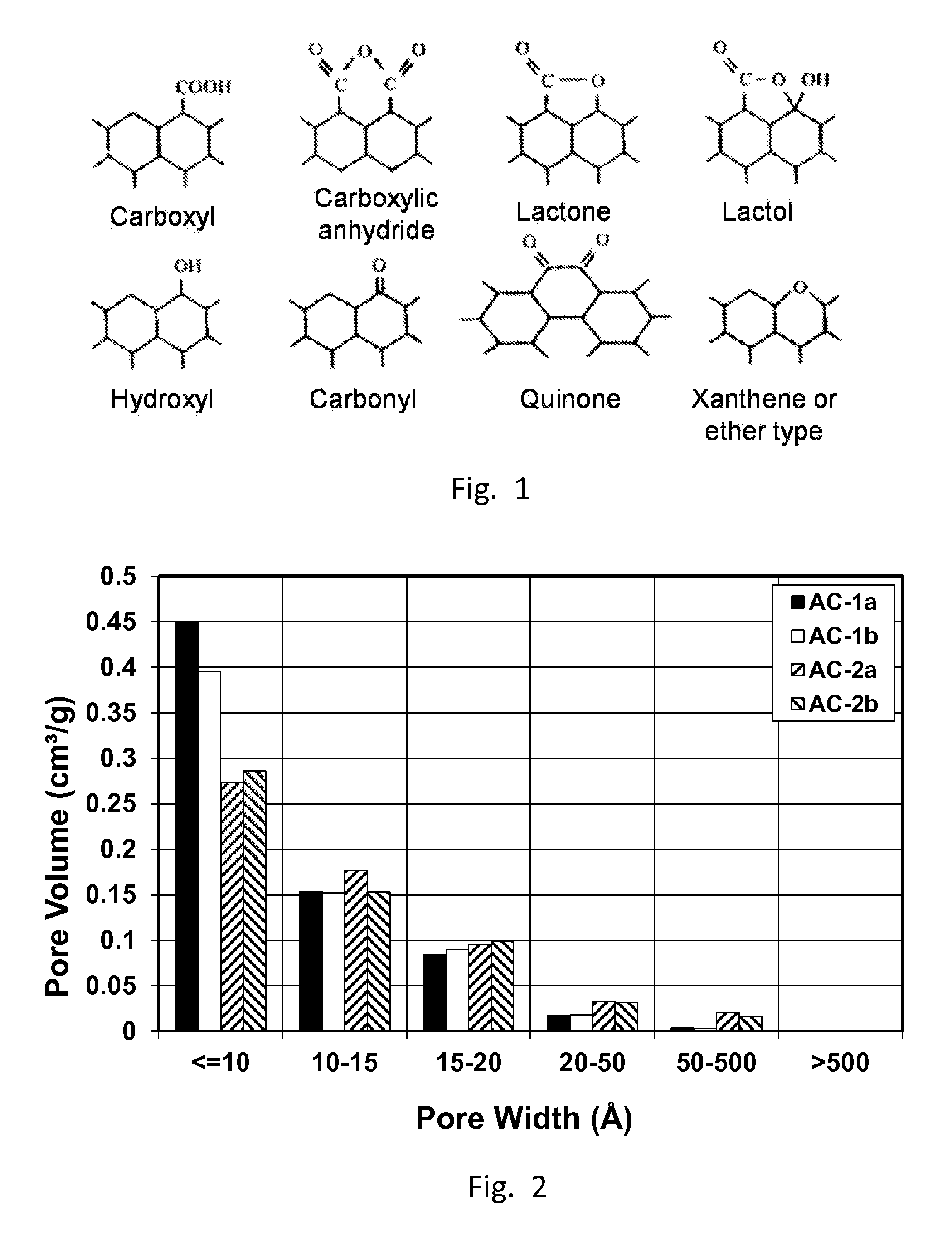
[0069]The activated carbon samples were characterized for total oxygen content using an elemental analyzer. The content of oxygen-containing surface functional groups was measured using Boehm titration. Results are summarized in Table 1 together with the oxygen content of the carbon black used to form the carbon-based electrodes.

TABLE 1Oxygen and surface functional group content of activated carbonCarboxylic+Lactone+DFT poreTreductionOxygenAnhydrideLactolHydroxylBETvolumeSample[° C.][wt. %][mm...

example 3

[0080]The total oxygen content of commercially-available carbon black (Black Pearls®, Cabot Corporation, Boston, Mass.) was reduced from 1.3 wt. % to about 0.4 wt. % by a reefing step that included heating the carbon black at 675° C. in a forming gas ambient (1% H2 in N2).


PUM


Abstract

A positive electrode for an energy storage device includes a first activated carbon material comprising pores having a size of ≦1 nm, which provide a combined pore volume of >0.3 cm3 / g, pores having a size of >1 nm to ≦2 nm, which provide a combined pore volume of ≧0.05 cm3 / g, and <0.15 cm3 / g combined pore volume of any pores having a size of >2 nm. A negative electrode for the energy storage device includes a second activated carbon material comprising pores having a size of ≦1 nm, which provide a combined pore volume of ≦0.3 cm3 / g, pores having a size of >1 nm to ≦2 nm, which provide a combined pore volume of ≧0.05 cm3 / g, and <0.15 cm3 / g combined pore volume of any pores having a size of >2 nm. The total oxygen content in at least the first activated carbon material is at most 1.5 wt. %.

Description

CROSS-REFERENCE TO RELATED APPLICATIONS[0001]This application claims the benefit of priority under 35 U.S.C. §119 of U.S. Application Ser. No. 61 / 877,341 filed on Sep. 13, 2013, and U.S. Application Ser. No. 61 / 872,202 filed on Aug. 30, 2013, the entire contents of which are hereby incorporated by reference.BACKGROUND[0002]1. Field[0003]The present disclosure relates generally carbon-based electrodes for energy storage devices, and more specifically to carbon-based electrodes exhibiting high-voltage stability and their methods of production.[0004]2. Technical Background[0005]Energy storage devices such as ultracapacitors may be used in a variety of applications such as where a discrete power pulse is required. Example applications range from cell phones to hybrid vehicles. Ultracapacitors such as electrochemical double layer capacitors (EDLCs) have emerged as an alternative or compliment to batteries in applications that require high power, long shelf life, and / or long cycle life. U...

Claims


Application Information

Patent Timeline
IPC IPC(8): H01G11/26H01G11/42H01G11/86H01M4/02H01M4/04H01M4/583H01M10/0568
CPCH01G11/26H01G11/42H01G11/86H01G11/24H01G11/32H01G11/34H01M4/133C01B32/15Y02T10/70Y02E60/10Y02P70/50Y02E60/13
Inventor GADKAREE, KISHOR PURUSHOTTAMLIU, JIA
Owner CORNING INC
Learn More