Enhanced coupling strength gratings

a technology of coupling strength and grating, which is applied in the field of can solve problems such as problematic generation of light on silicon wafers, and achieve the effects of enhancing the coupling strength of gratings, high index, and enhanced coupling strength gratings

Active Publication Date: 2015-03-05
ORACLE INT CORP +1
View PDF34 Cites 63 Cited by
  • Summary
  • Abstract
  • Description
  • Claims
  • Application Information

AI Technical Summary

Benefits of technology

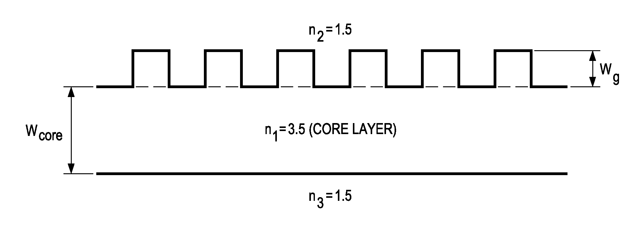
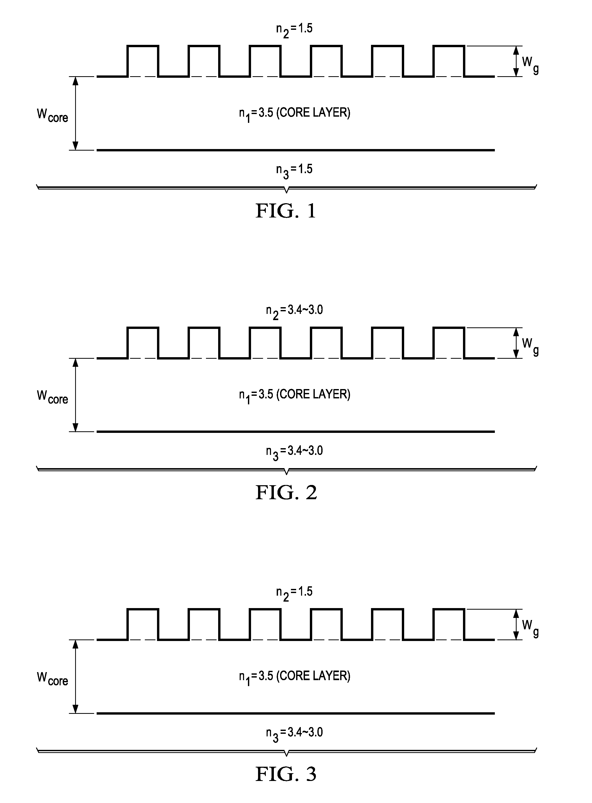
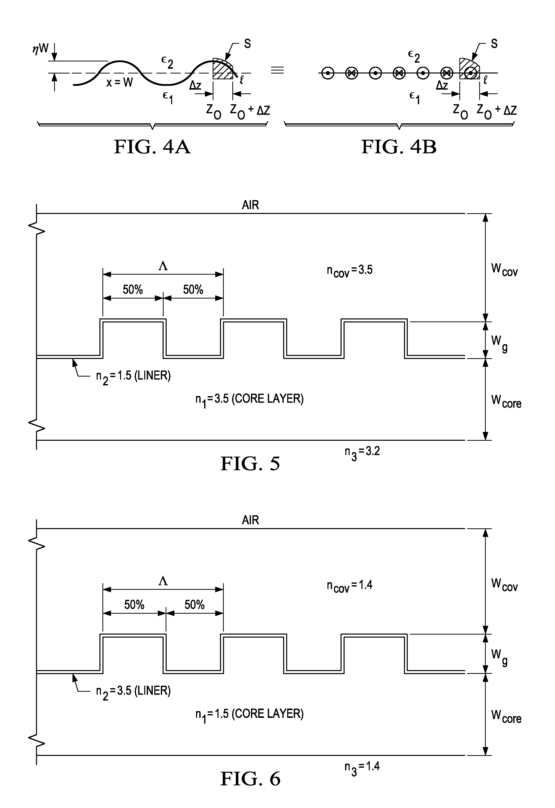
[0012]The present invention describes devices and methods for enhancing the coupling strength of gratings formed in dielectric waveguides of all types, including optical waveguides formed in compound semiconductor waveguides and optical waveguides formed in glasses and used for fiber optics. Such Enhanced Coupling Strength (ECS) gratings in compound semiconductor waveguides can match the performance of gratings in high index contrast silicon / silicon dioxide optical waveguides. In particular, ECS gratings couple power in very short distances compared to common gratings in semiconductor waveguides.

Problems solved by technology

However, generating light on a silicon wafer is problematic.

Method used


Image

  • Enhanced coupling strength gratings
  • Enhanced coupling strength gratings
  • Enhanced coupling strength gratings

Examples


Embodiment Construction

[0066]While the making and using of various embodiments of the present invention are discussed in detail below, it should be appreciated that the present invention provides many applicable inventive concepts that can be embodied in a wide variety of specific contexts. The specific embodiments discussed herein are merely illustrative of specific ways to make and use the invention and do not delimit the scope of the invention.

[0067]To facilitate the understanding of this invention, a number of terms are defined below. Terms defined herein have meanings as commonly understood by a person of ordinary skill in the areas relevant to the present invention. Terms such as “a”, “an” and “the” are not intended to refer to only a singular entity, but include the general class of which a specific example may be used for illustration. The terminology herein is used to describe specific embodiments of the invention, but their usage does not delimit the invention, except as outlined in the claims.

[...


PUM

PropertyMeasurementUnit
reflectivityaaaaaaaaaa
in-plane reflectivityaaaaaaaaaa
refractive indexaaaaaaaaaa

Abstract

The present invention includes an optical waveguide with a grating and a method of making the same for increasing the effectiveness of the grating. In one example, the grating is at least partially covered by a liner layer disposed on at least a portion of a grating; and a cover layer disposed on the liner layer, wherein a first material selected for the core and ridges and a second material selected for the liner layer are selected to provide a difference in the index of refraction between the first and second material that is sufficient to provide a contrast therebetween.

Description

CROSS-REFERENCE TO RELATED APPLICATIONS[0001]This application claims priority based on U.S. provisional Application No. 61 / 874,162, filed Sep. 5, 2013. The contents of which is incorporated by reference in its entirety.STATEMENT OF FEDERALLY FUNDED RESEARCH[0002]This invention was made with Government support under Agreement No. HR0011-08-9-0001 awarded by DARPA. The Government has certain rights in the invention.TECHNICAL FIELD OF THE INVENTION[0003]The present invention relates in general to the field of electromagnetic radiation, and more particularly, to an apparatus and methods to enhance the coupling strength of electromagnetic radiation coupled by gratings in optical waveguides.BACKGROUND OF THE INVENTION[0004]Without limiting the scope of the invention, its background is described in connection with optical waveguides.[0005]High index contrast silicon / silicon dioxide optical waveguides can radiate 60 to 100% of the light propagating in the waveguide from a grating etched int...

Claims


Application Information

Patent Timeline
Patent Type & Authority Applications(United States)
IPC IPC(8): G02B6/34G02B6/132G02B6/136G02B6/036H01S5/12
CPCG02B6/34G02B6/036G02B2006/12176G02B6/136G02B6/132G02B6/1223G02B2006/12107H01S3/0635H01S5/12H01S5/1231H01S5/125H01S5/187
Inventor EVANS, GARY A.BUTLER, JEROME K.KIRK, JAY B.HE, RUO-HUAYAO, JINLI, GUOLIANGZHENG, XUEZHEKRISHNAMOORTHY, ASHOK V.
Owner ORACLE INT CORP
Why Eureka
Try Eureka