Fuel cell assembly and method of manufacturing same, and bonding part manufacturing method and device
Active Publication Date: 2015-03-05
HONDA MOTOR CO LTD
View PDF6 Cites 15 Cited by
Summary
Abstract
Description
Claims
Application Information
AI Technical Summary
This helps you quickly interpret patents by identifying the three key elements:
Problems solved by technology
Method used
Benefits of technology
[0058]In this structure, heat of the heating member is transferred through the pressing member to the facing portion, thereby preventing occurrence of the aforementioned stringing effect. Consequently, a joined assembly (such as a fuel cell assembly) can be efficiently produced without requiring after-treatments to compensate for stringing.
[0059]Preferably,
Problems solved by technology
As a practical matter, it is difficult to sufficiently melt the resin frame 11.
Furthermore, the electrolyte me
Method used
Image
Click on the blue label to locate the original text in one second.
Reading with bidirectional positioning of images and text.
Examples
second embodiment
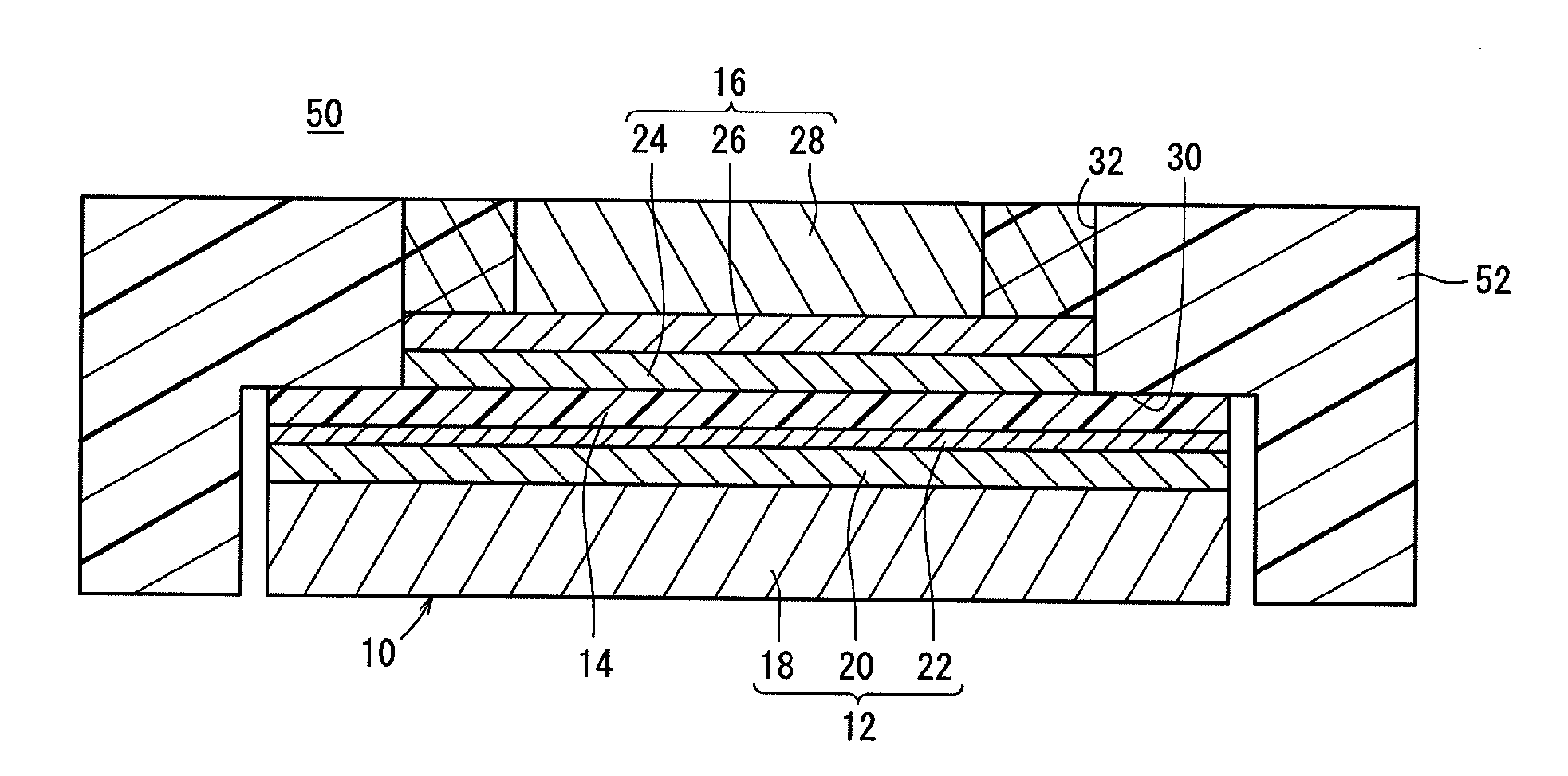
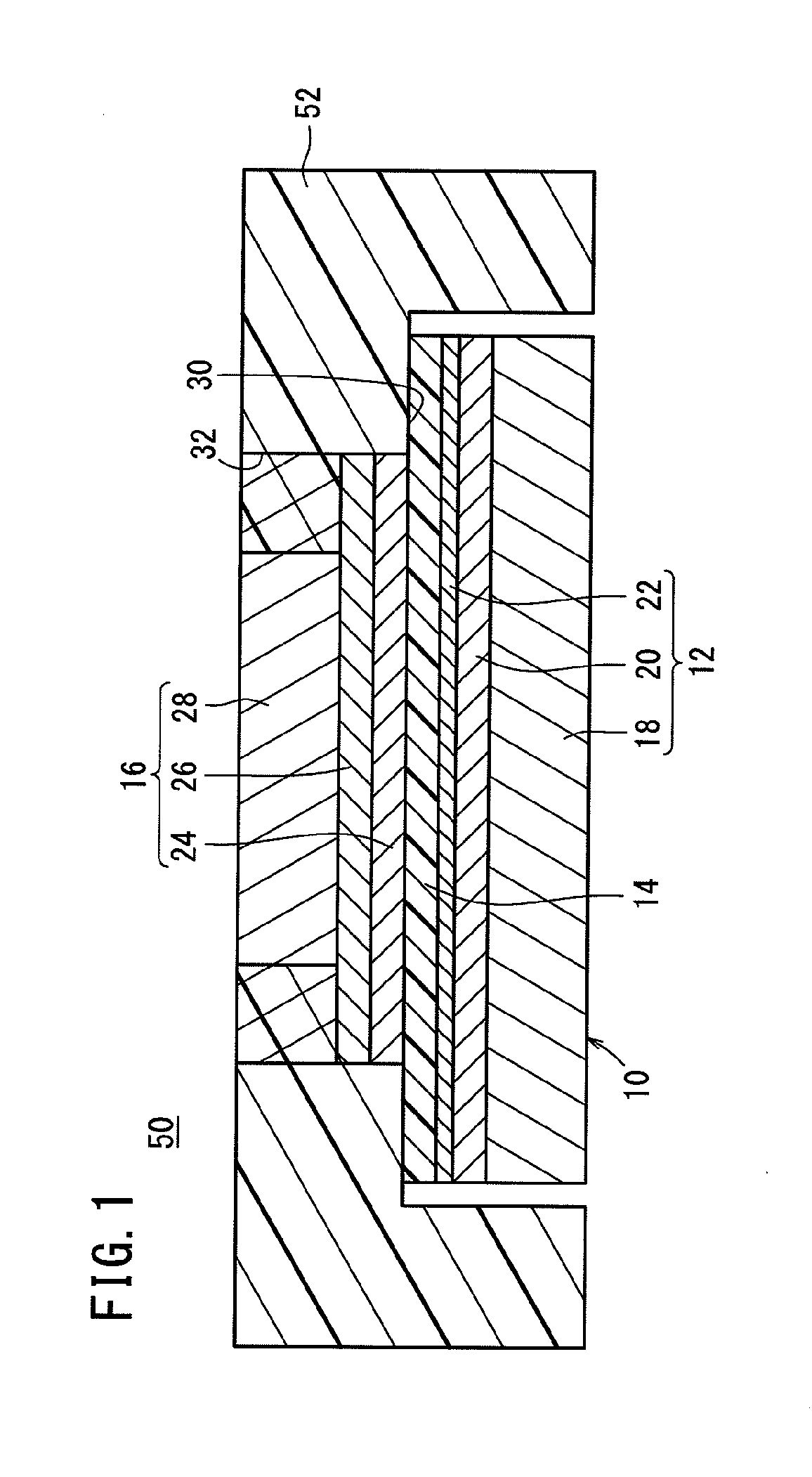
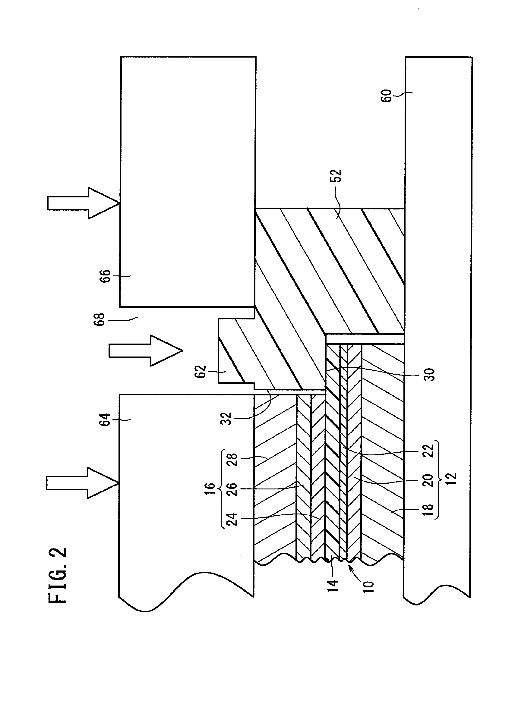
[0096]A protrusion 62 is formed beforehand on the upper surface of the resin frame 52 in the vicinity of the recess 30. The protrusion 62 may be molded integrally with the resin frame 52. Alternatively, the protrusion 62 may be formed by so-called padding in the vicinity of the recess 30. As will be described in the second embodiment, it is also preferred that a trap recess is formed in the vicinity of the protrusion 62.
[0097]A first heat radiating press mold 64 and a second heat radiating press mold 66 are placed respectively on the gas diffusion layer 28 of the anode 16 and on the upper surface of the resin frame 52. A clearance 68 is formed between the first heat radiating press mold 64 and the second heat radiating press mold 66. The protrusion 62 is located in the clearance 68.
[0098]Next, the protrusion 62 is heated and pressed. During this step, for example, laser irradiation, infrared ray irradiation, or the like may be carried out. Alternatively, a heated jig such as a hot p...
first embodiment
[0120]Similar to the first embodiment, the bottom surface of the recess 30 may be placed in contact solely with the lower surface of the electrolyte membrane 14 in facing relation to the bottom surface, and may be bonded to the electrolyte membrane 14 by an adhesive or the like.
[0121]A bonding apparatus for producing the resin frame 82 will be described with reference to FIGS. 9 to 16. The fuel cell assembly 50 of the first embodiment can also be produced by the bonding apparatus.
[0122]FIG. 9 is a schematic partially vertical cross-sectional front view of a bonding apparatus 90 according to the second embodiment. Hereinafter, the terms “bottom”, “top”, “left”, and “right” will be used to imply the bottom, top, left, and right of the drawings, respectively.
[0123]The bonding apparatus 90 includes a first die base 92, a second die base 94, and a positioning jig 96. The membrane electrode assembly 10 and the resin frame 82 are placed on the positioning jig 96. At this time, the outer pe...
PUM
Property
Measurement
Unit
Pressure
aaaaa
aaaaa
Area
aaaaa
aaaaa
Abstract
The present invention relates to a fuel cell assembly and method of manufacturing same, and a bonding part manufacturing method and device. For instance, in a resin frame, a depression part is subsidence formed from a lower-end face toward an upper-end face, and a housing hole is pass-through formed from a top surface of the depression part toward the upper-end face. For instance, the depression part, a cathode-side electrode and an electrolyte film are housed, and in such a circumstance, an anode-side electrode is housed in the housing hole. A portion of the resin frame permeates a gas diffusion layer which configures the anode-side electrode and is a porous body. Via the permeated site, the resin frame and the gas diffusion layer (anode-side electrode) are integrally bonded.
Description
TECHNICAL FIELD[0001]The present invention relates to a fuel cell assembly, and a method for producing (manufacturing) the same. The fuel cell assembly contains a membrane electrode assembly containing an anode and a cathode with a solid polymer electrolyte membrane interposed therebetween. The fuel cell assembly further contains a resin frame for supporting the membrane electrode assembly. The present invention further relates to a method and an apparatus (device) for producing a joined assembly (manufacturing a bonding part) by bonding a porous member made of a porous body and a resin member to each other.BACKGROUND ART[0002]A solid polymer electrolyte fuel cell contains a membrane electrode assembly prepared by interposing a solid polymer electrolyte membrane between an anode and a cathode. In this type of fuel cell, the membrane electrode assembly, and a resin frame for supporting the membrane electrode assembly may be integrally bonded to obtain a fuel cell assembly. A pluralit...
Claims
Application Information
Patent Timeline
Application Date:The date an application was filed.
Publication Date:The date a patent or application was officially published.
First Publication Date:The earliest publication date of a patent with the same application number.
Issue Date:Publication date of the patent grant document.
PCT Entry Date:The Entry date of PCT National Phase.
Estimated Expiry Date:The statutory expiry date of a patent right according to the Patent Law, and it is the longest term of protection that the patent right can achieve without the termination of the patent right due to other reasons(Term extension factor has been taken into account ).
Invalid Date:Actual expiry date is based on effective date or publication date of legal transaction data of invalid patent.