Centrifugal filtration device and cell separation system with the same

a centrifugal filtration and cell separation technology, applied in the field of biological cell separation, can solve the problems of mechanical trauma and pollution of cells, increase the cost of cell separation, and affect the quality of cells, so as to reduce cell damage, reduce the cost of cell separation, and facilitate operation.

Inactive Publication Date: 2015-03-12
ZHENG CHONG
View PDF10 Cites 8 Cited by
  • Summary
  • Abstract
  • Description
  • Claims
  • Application Information

AI Technical Summary

Benefits of technology

[0025]The advantage of the present invention is that: the centrifugal filtration device and the cell separation system having said centrifugal filtration device with simple structure and easy operation, are capable of separating cells rapidly in a fully sealed system, which decreases cell damage during the separation process, and avoids cell population, the cell separation process could be automatically controlled by the computer, and the cell separation system has low demand in laboratory.
is that: the centrifugal filtration device and the cell separation system having said centrifugal filtration device with simple structure and easy operation, are capable of separating cells rapidly in a fully sealed system, which decreases cell damage during the separation process, and avoids cell population, the cell separation process could be automatically controlled by the computer, and the cell separation system has low demand in laboratory.

Problems solved by technology

In prior art, cell separation is carried out by centrifuges; this separating method not only has fussy operation, but also results in mechanical trauma and pollution to cell, owing to the operation which requires drawing out and putting in cell sap again and again, and this kind of operation is strict with the laboratory environment, which impacts cell quality, and increases cost for cell separation.

Method used


Image

  • Centrifugal filtration device and cell separation system with the same
  • Centrifugal filtration device and cell separation system with the same
  • Centrifugal filtration device and cell separation system with the same

Examples


Embodiment Construction

[0031]The embodiments of the present invention are disclosed in detail by combining with figures below. All the following are the preferred embodiments of the present invention, which is not the limitation of the protection of the present invention.

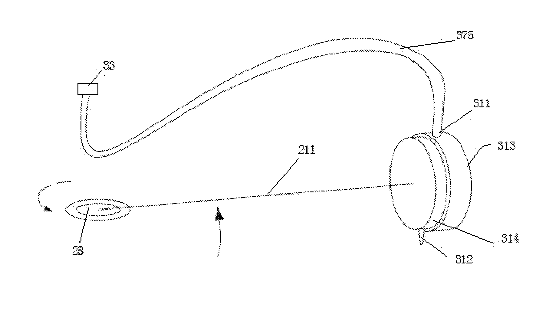
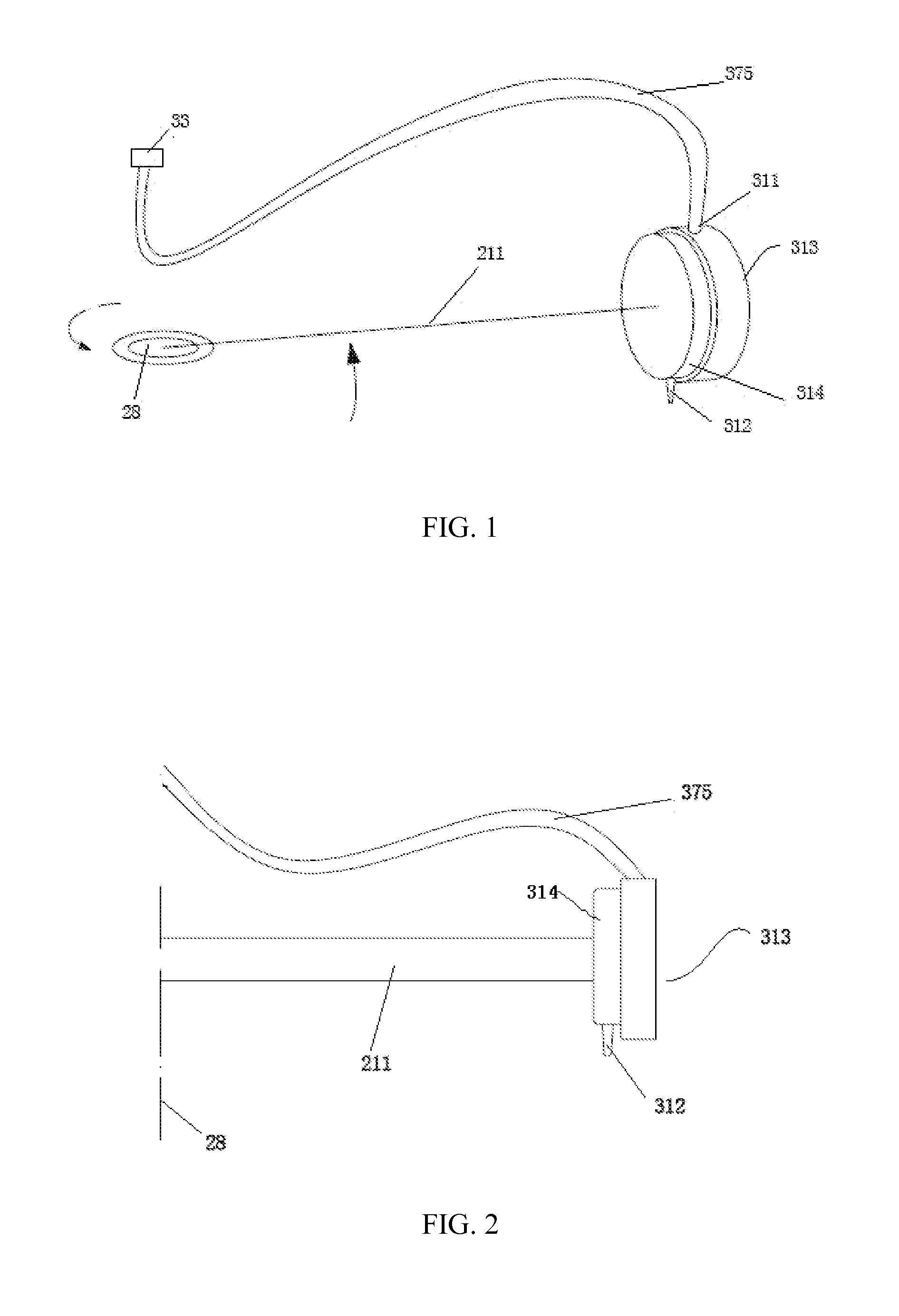
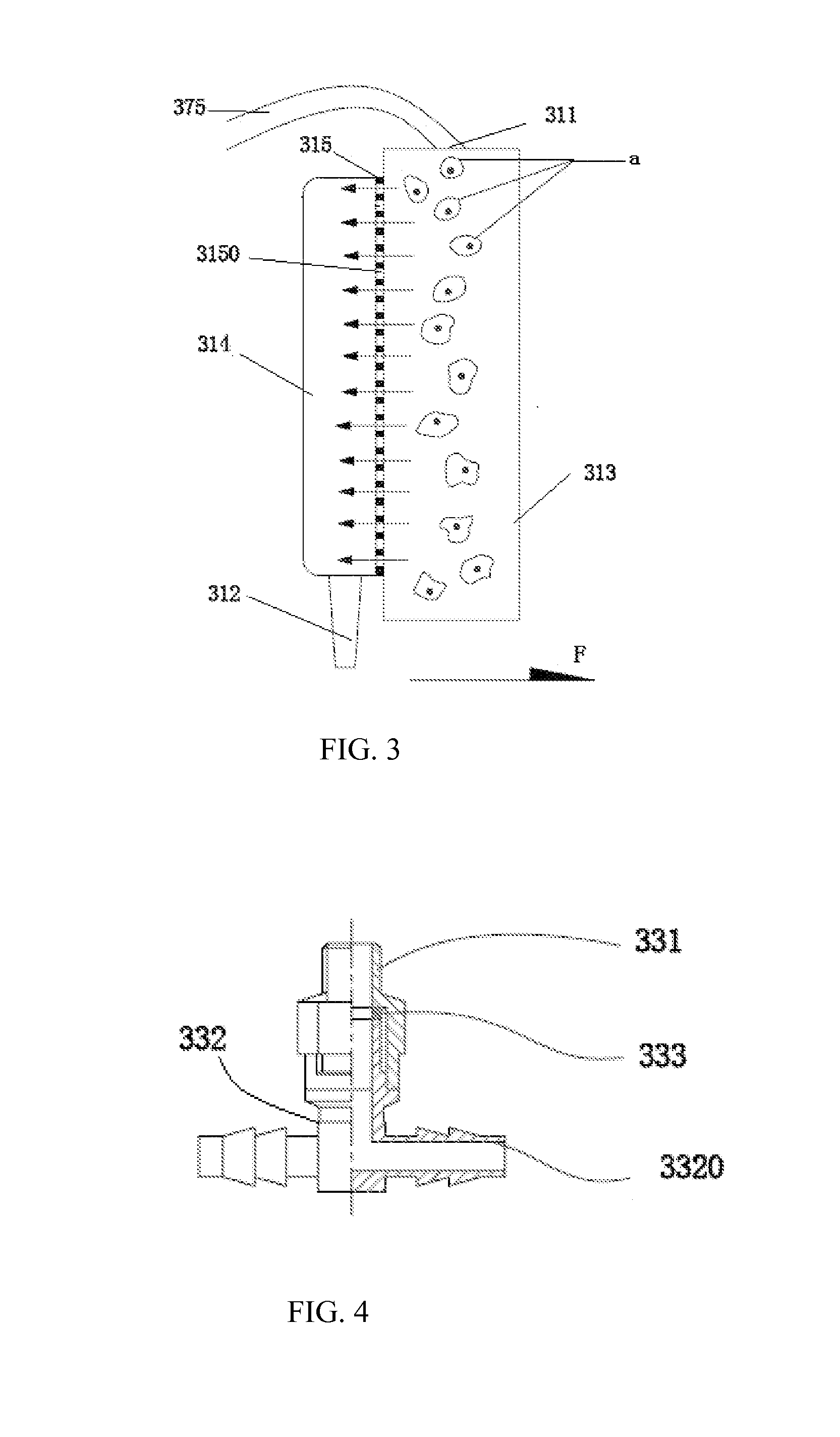
[0032]FIGS. 1, 2 and 3 show the centrifugal filtration device according to an embodiment of the present invention, and the centrifugal filtration device for separating cells includes a spindle 28, a rotary arm 211 which is connected vertically to the spindle and rotating as the spindle rotates, and a microporous membrane filter 31 which is mounted on a far end referring to the rotary arm.

[0033]The microporous membrane filter 31 includes an inlet 311, an outlet 312, a front cavity 313 communicated to the inlet, a rear cavity 314 communicated to the outlet, and a filter membrane 315 arranged between the front cavity 313 and the rear cavity 314. Preferably, the inlet 311 is formed at the top of the front cavity 313, and the outlet 312 is for...


PUM

PropertyMeasurementUnit
lengthaaaaaaaaaa
diameteraaaaaaaaaa
diameteraaaaaaaaaa

Abstract

The present invention directs to a centrifugal filtration device, for separating living cells, including a spindle (28), a rotary arm (211) which is connected vertically to the spindle (28) and rotates as the spindle rotates, and a microporous membrane filter (31) which is mounted on the rotary arm (211). The microporous membrane filter (31) includes an inlet (311), an outlet (312), a front cavity (313) having the inlet (311) formed thereon, a rear cavity (314) having the outlet (312) formed thereon, and a filter membrane (315) arranged between the front cavity and the rear cavity; the diameter of each filter pore formed in the filter membrane is smaller than that of the cell which needs to be separated. The present invention also discloses a cell separation system.

Description

CROSS-REFERENCE TO RELATED APPLICATIONS[0001]This present application is a Continuation Application of PCT application No. PCT / CN2012 / 086694 filed on Dec. 14, 2012, the contents of which are hereby incorporated by reference.FIELD OF THE INVENTION[0002]The present invention relates to biological cell separation field, especially for a centrifugal filtration device and a cell separation system having a microporous membrane filter, and a rapid cell separation method is obtained by using this system.BACKGROUND OF THE INVENTION[0003]The best treatment of disease is reconstruction of living tissue and growing tissue which is worn out by old age or disease into new tissue, this treatment is called “Cell Treatment”. The cell treatment has a century's history, and is widely used in all filed of tumor treatment, liver treatment and dermabrasion, and it has vast development prospects.[0004]The basic question for cell treatment is separating target cell. In prior art, cell separation is carried...

Claims


Application Information

Patent Timeline
Patent Type & Authority Applications(United States)
IPC IPC(8): B01D33/067B01D33/80
CPCB01D33/804B01D33/067B01D61/18B01D63/16B01D2315/02C12M1/123
Inventor ZHENG, CHONG
Owner ZHENG CHONG
Why Eureka
Try Eureka