Process for treating an effluent for the purpose of bringing down the phosphate content thereof, comprising a step of optimized wet heat treatment, and corresponding equipment

a technology of wet heat treatment and effluent, which is applied in the direction of water/sludge/sewage treatment, filtration separation, specific water treatment objectives, etc., can solve the problems of increasing the quantity of sludge formed during the treatment of water, having a negative environmental impact in terms of carbon footprint, and requiring the use of additional, bulky and costly technical means dedicated solely to production, so as to promote paos and reduce phosphates

Inactive Publication Date: 2015-03-12
VEOLIA WATER SOLUTIONS & TECH SUPPORT
View PDF3 Cites 10 Cited by
  • Summary
  • Abstract
  • Description
  • Claims
  • Application Information

AI Technical Summary

Benefits of technology

[0014]Implementing these techniques does indeed enable the introduction of more VFAs into the eff...

Problems solved by technology

However, municipal waste water generally contains an excessively small quantity of VFAs so that carrying out biological dephosphatation eliminates a limited quantity of phosphates and therefore does not eliminate as much of phosphates as is required.
While resorting to the use of such reagents has the advantage of appropriately reducing the phosphates, it ne...

Method used


Image

  • Process for treating an effluent for the purpose of bringing down the phosphate content thereof, comprising a step of optimized wet heat treatment, and corresponding equipment
  • Process for treating an effluent for the purpose of bringing down the phosphate content thereof, comprising a step of optimized wet heat treatment, and corresponding equipment
  • Process for treating an effluent for the purpose of bringing down the phosphate content thereof, comprising a step of optimized wet heat treatment, and corresponding equipment

Examples


first embodiment

7.2. Example of the Invention

[0074]7.2.1. Plant

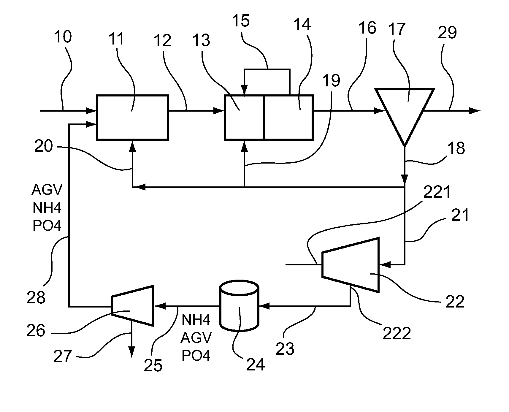
[0075]Referring to FIG. 1, we present an embodiment of a plant for treating water according to the invention.

[0076]Thus, as represented in this figure, such a plant comprises a pipe 10 for conveying water to be treated. This pipe 10 leads into the inlet of an anaerobic biological treatment zone 11.

[0077]This anaerobic biological treatment zone 11 comprises a biological reactor within which dephosphating PAO microorganisms develop when anaerobic conditions are maintained. This treatment zone 11 comprises an outlet which is connected by means of a pipe 12 to the inlet of an anoxic biological treatment zone 13.

[0078]An anoxic biological treatment zone 13 comprises a biological reactor within which denitrifying microorganisms develop when anoxic conditions are maintained. This anoxic biological treatment zone 13 comprises an outlet which is connected to the inlet of an aerobic biological treatment zone 14.

[0079]This aerobic biological treat...

second embodiment

7.3. Example of the Invention

[0110]7.3.1. Plant

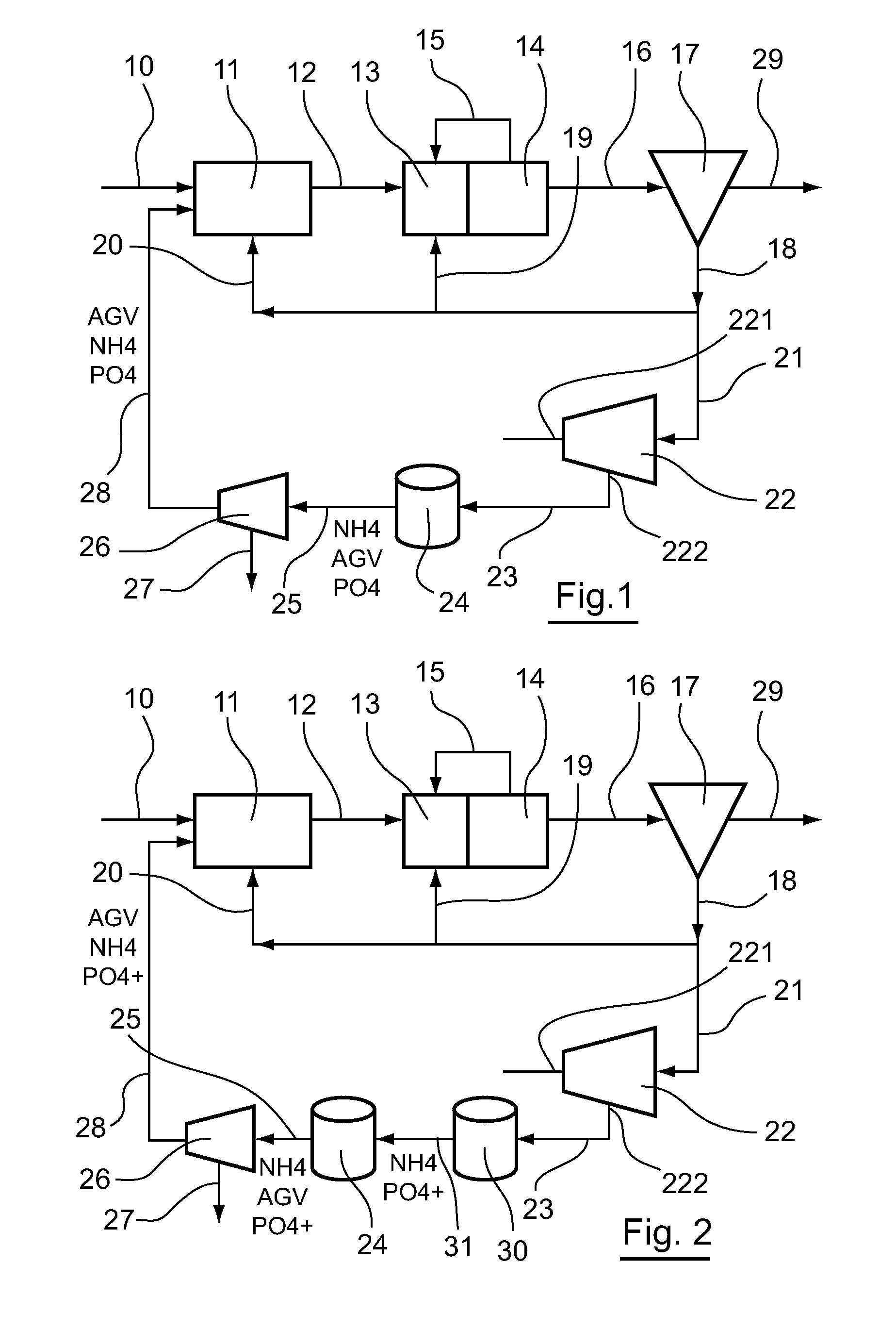
[0111]Referring to FIG. 2, we present a plant according to a second embodiment.

[0112]The plant illustrated in FIG. 2 is distinguished from the one illustrated in FIG. 1 by the fact that it comprises in addition an anaerobic digester 30 interposed between the outlet of the concentrator 22 and the inlet of the wet heat treatment 24, to the inlet of which it is connected by means of a pipe 31.

[0113]7.3.2. Method

[0114]An example of a method according to the invention implementing a plant described with reference to FIG. 2 is now described.

[0115]Such a method is distinguished from the one described here above by the fact that the concentrated sludges coming from the concentrator 22 are conveyed via the pipe 23 to the anaerobic digester 30.

[0116]These sludges therein undergo an anaerobic digestion which leads to the formation and extraction of biogas and a sludge containing residual organic matter, ammoniacal nitrogen and phosphates. This slu...

third embodiment

7.4. Example of the Invention

[0118]7.4.1. Plant

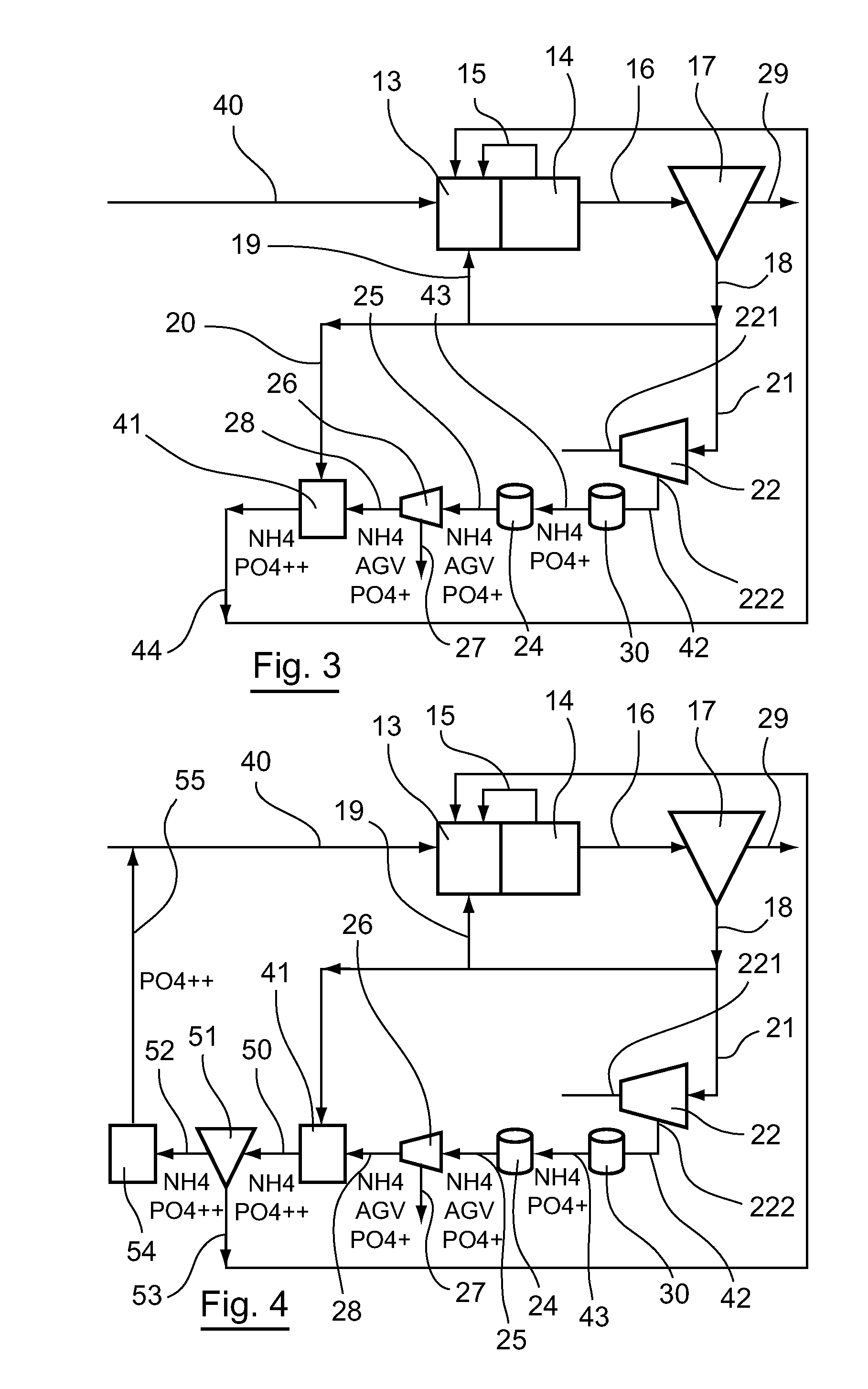
[0119]Referring to FIG. 3, we present a plant according to a third embodiment.

[0120]As shown in this FIG. 3, such a plant comprises a water inlet pipe 40. This pipe 40 leads into the inlet of an anoxic biological treatment zone 13.

[0121]This anoxic biological treatment zone 13 comprises a biological reactor within which anoxic conditions are maintained so that the development of denitrifying microorganisms is fostered. This anoxic biological treatment zone 13 comprises an outlet that is connected to the inlet of an aerobic biological treatment zone 14.

[0122]This aerobic biological treatment zone 14 comprises a biological reactor that houses aeration means such as an air or oxygen distributor, within which aerobic conditions are maintained so that the development of the nitrifying microorganisms is promoted. This aerobic biological treatment zone 14 comprises a first outlet that is linked via a recirculation pipe 15 to the anoxic biologi...


PUM

PropertyMeasurementUnit
Temperatureaaaaaaaaaa

Abstract

The invention pertains to a method for treating an effluent to be treated in order to reduce its phosphates content, said method comprising a step of anoxic biological treatment of said effluent to be treated, producing a first effluent, a step of aerobic biological treatment of said first effluent, producing a second effluent, a step of recirculating at least a part of said second effluent to the inlet of said anoxic biological treatment step, a step of liquid/solid separation of at least a part of said second effluent, producing a treated effluent and a first denser effluent, a step for producing volatile fatty acids including a wet heat treatment, at a temperature of 100° C. to 350° C., for a residence time of between 10 and 180 minutes, of at least a part of said first denser effluent, a step of anaerobic biological treatment of at least a part of the effluent coming from said wet heat treatment step, and a step of recirculating at least a part of the effluent coming from said anaerobic biological treatment step to the inlet of said anoxic biological treatment step.

Description

[0001]This application is a U.S. National Stage Application of PCT Application No. PCT / EP2013 / 051469, with an international filing date of 25 Jan. 2013. Applicant claims priority based on French Patent Application No. 1250822 filed 27 Jan. 2012. The subject matter of these applications is incorporated herein.1. FIELD OF THE INVENTION[0002]The field of the invention is that of methods and plants for treating effluents by biological process and purification sludges obtained by the biological treatment of the effluents.[0003]The invention especially pertains to the methods for treating waste water in order to reduce its phosphates content.2. PRIOR ART[0004]For many years now, techniques for treating waste water, for example municipal waste water, have been developed and implemented with the goal of discarding sanitized waste water into the natural environment.[0005]These modes of treatment are aimed especially at reducing the content in nutrients, especially nitrogen and phosphorus, of...

Claims


Application Information

Patent Timeline
IPC IPC(8): C02F3/30C02F1/72
CPCC02F3/308C02F1/725C02F2301/046C02F2101/322C02F2101/105C02F3/1221C02F3/307C02F11/04C02F11/08C02F2001/5218C02F2101/16C02F2303/06Y02W10/10
Inventor LEMAIRE, ROMAINCHAUZY, JULIENDJAFER, MALIK
Owner VEOLIA WATER SOLUTIONS & TECH SUPPORT
Why Eureka
Try Eureka