Systems and methods for injecting gaseous fuel during an exhaust stroke to reduce turbo lag

a technology of gaseous fuel and turbo lag, which is applied in the direction of electric control, ignition automatic control, machines/engines, etc., can solve the problems of reducing the responsiveness of the vehicle, reducing the power supply of the engine, and lag in the turbo, so as to increase the power output of the engine, increase the speed of the compressor, and increase the boost

Active Publication Date: 2015-03-19
FORD GLOBAL TECH LLC
View PDF0 Cites 31 Cited by
  • Summary
  • Abstract
  • Description
  • Claims
  • Application Information

AI Technical Summary

Benefits of technology

[0002]Turbocharged engines utilize a turbocharger to compress intake air and increase the power output of the engine. A turbocharger may use an exhaust-driven turbine to drive a compressor which compresses intake air. As the speed of the compressor increases, increased boost is provided to the engine. During transient conditions, upon receiving an increased torque demand, there may be a delay in turbocharger response before the turbine and compressor speed is increased to a desired sp...

Problems solved by technology

This delay in turbocharger response, termed turbo lag, may result in a delay in providing the demanded engine power.
For example, during vehicle launch conditions, such as when accelerating from idle, minimal exhaust gas flow combined with increased load on the compressor may result in turbo lag.
Consequently, when accelerating from idle speed, turbo lag may decrease responsiveness of the vehicle to driver's torque demand, and thus decrease driving control.
However, inventors herein have ident...

Method used


Image

  • Systems and methods for injecting gaseous fuel during an exhaust stroke to reduce turbo lag
  • Systems and methods for injecting gaseous fuel during an exhaust stroke to reduce turbo lag
  • Systems and methods for injecting gaseous fuel during an exhaust stroke to reduce turbo lag

Examples


Embodiment Construction

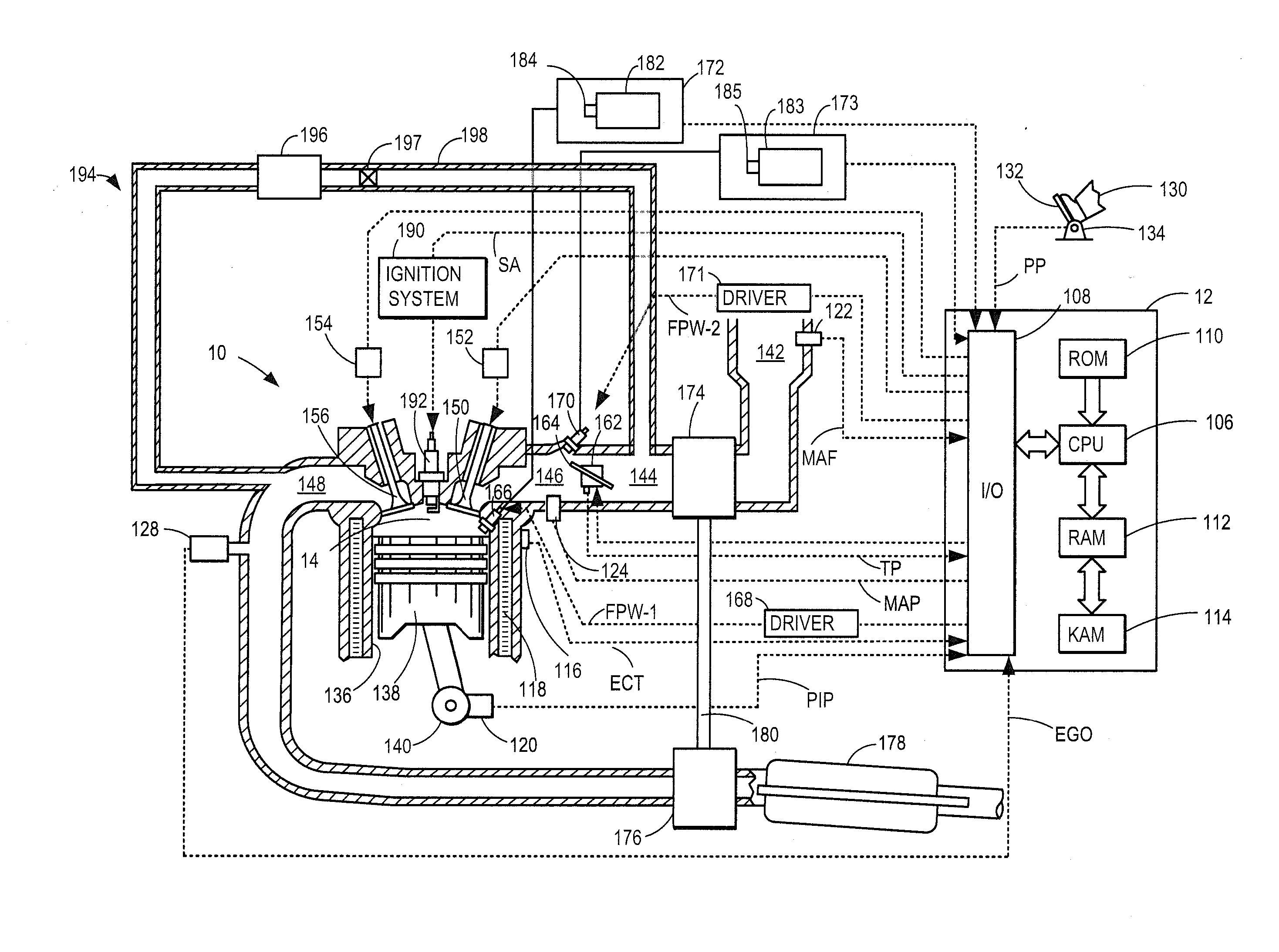
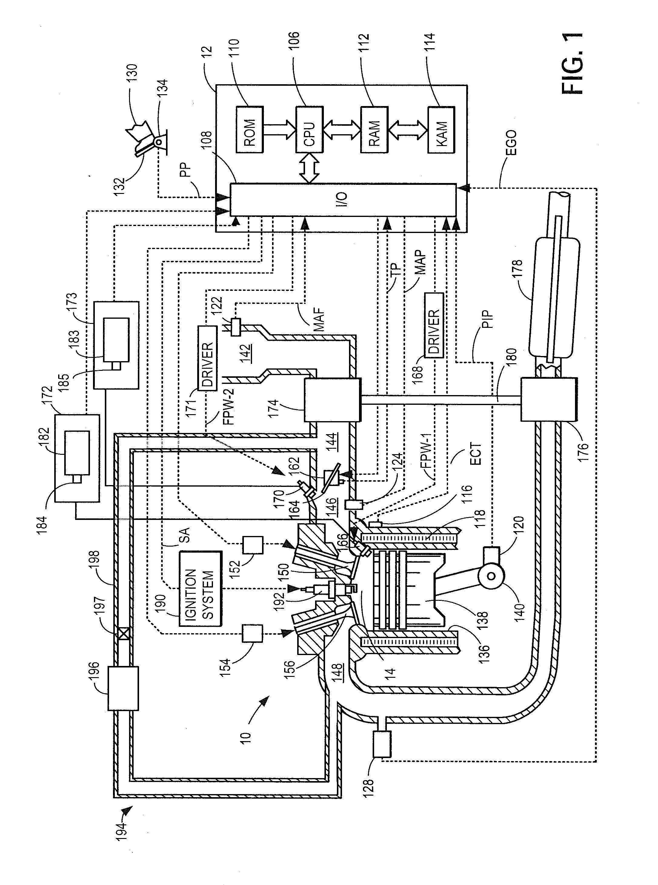
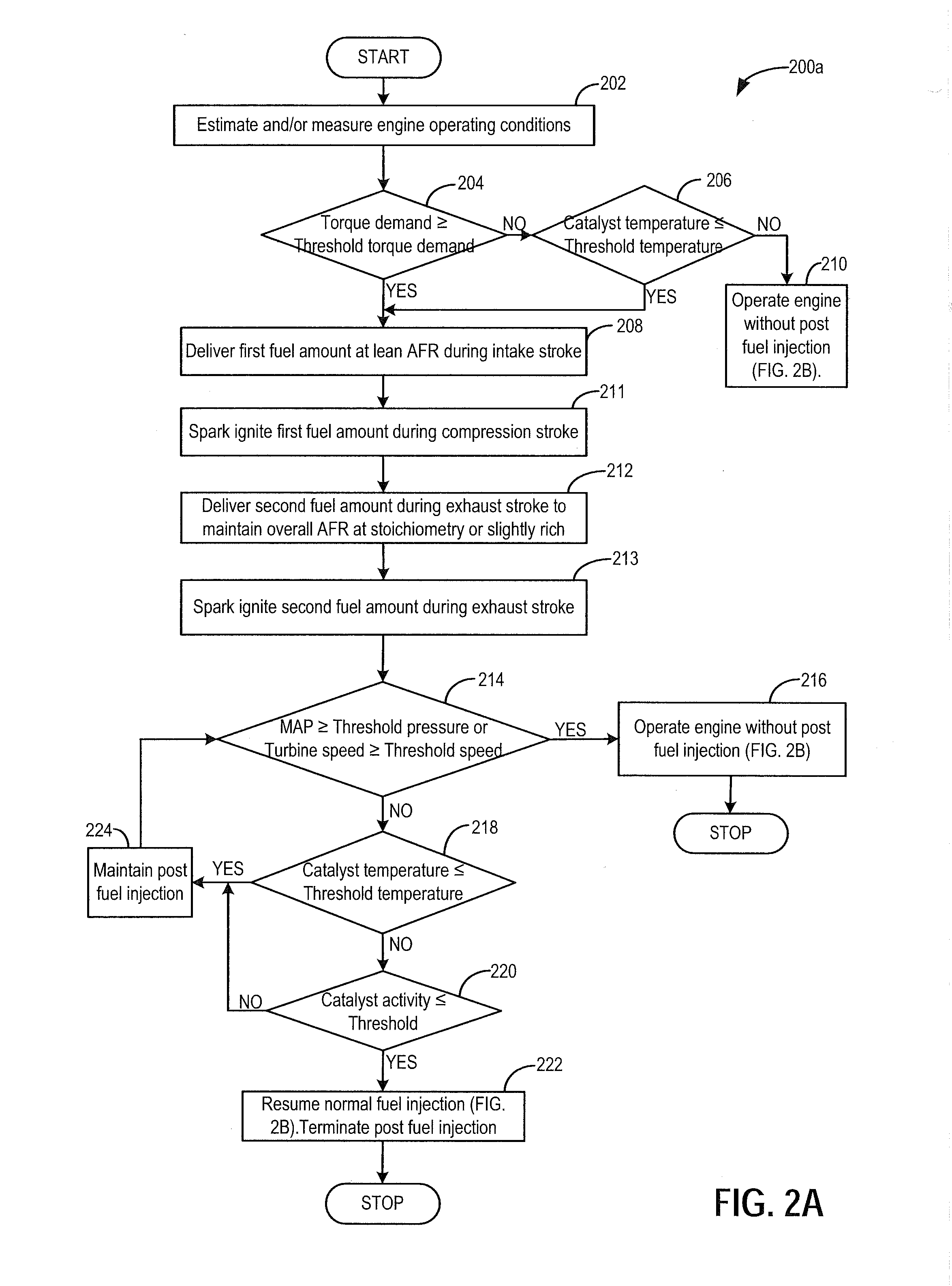
[0016]The present description relates to an engine system configured to deliver gaseous fuel. In one non-limiting example, the engine may be configured as part of the system illustrated in FIG. 1, wherein the engine includes at least one cylinder, a control system, and a turbocharger among other features. Turbocharged engines may experience turbo lag (that is, a delay before a turbine speed increases to a threshold speed to provide demanded torque output). A method for reducing turbo lag (shown at FIG. 2A) includes combusting a first fuel amount during a compression stroke of a cylinder combustion event, and subsequently combusting a second fuel amount during an exhaust stroke. Injecting and combusting a second amount of a fuel during an exhaust stroke may be referred to as post fuel injection. Post fuel injection and combustion may be adjusted based on engine operating conditions, including torque demand, as described at FIG. 3. When post fuel injections are not performed, the engi...


PUM


Abstract

Methods and systems are provided for injecting and combusting an amount of gaseous fuel during an exhaust stroke of a cylinder combustion event in order to reduce turbo lag and reduce a duration of time required for an exhaust catalyst to light-off during transient events. In one example, when an increase in torque demand is greater than a threshold, a first amount of gaseous fuel may be combusted during a compression stroke of a cylinder combustion event and a second amount of gaseous fuel may be combusted during an exhaust stroke of the combustion event. The second amount may be adjusted based on the increase in torque demand.

Description

TECHNICAL FIELD [0001]The present application relates to methods and systems for reducing turbo lag in a boosted engine system with a liquefied petroleum gas (LPG) fuel delivery system.BACKGROUND AND SUMMARY[0002]Turbocharged engines utilize a turbocharger to compress intake air and increase the power output of the engine. A turbocharger may use an exhaust-driven turbine to drive a compressor which compresses intake air. As the speed of the compressor increases, increased boost is provided to the engine. During transient conditions, upon receiving an increased torque demand, there may be a delay in turbocharger response before the turbine and compressor speed is increased to a desired speed to provide the required boost. This delay in turbocharger response, termed turbo lag, may result in a delay in providing the demanded engine power. For example, during vehicle launch conditions, such as when accelerating from idle, minimal exhaust gas flow combined with increased load on the com...

Claims


Application Information

Patent Timeline
IPC IPC(8): F02D41/30
CPCF02D41/30F02D41/0007F02D41/0025F02D41/0027F02D41/3094F02D41/34F02D41/402F02P5/045F02P5/1527Y02T10/12Y02T10/40F02P5/145
Inventor GLUGLA, CHRIS PAULHEDGES, JOHN
Owner FORD GLOBAL TECH LLC
Why Eureka
Try Eureka