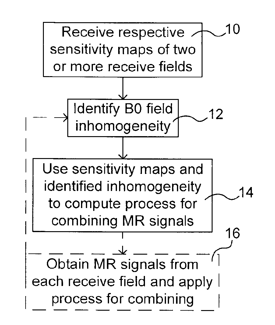
Method for B0 Field Correction in Magnetic Resonance
a magnetic resonance and field correction technology, applied in the field of b0 field correction in magnetic resonance, can solve problems such as time-varying errors, and achieve the effect of improving the homogeneity of b0 field
- Summary
- Abstract
- Description
- Claims
- Application Information
AI Technical Summary
Benefits of technology
Problems solved by technology
Method used
Image

Examples
case 1
Correcting a Linear Static B0 Gradient
[0062]The first example of an inhomogeneity that can be corrected is the case of an imperfectly shimmed B0 field. An unshimmed linear, constant B0-field gradient, i.e. appearing as B0ERR=xGx. Substituting this into EQ4 yields mCORR=mACT(r,t) exp [iγ(1−σ)xGxt], as the integral is trivial with Gx being a constant. Substitution into EQ7 yields B1CORR(r,t)=B1STATIC(r)·exp [−iγ(1−σ)xGxt]. By construction the emf resulting from using B1CORR as a detector field will cancel out the error term, so that ωEMF=ω0+ωEXPT. The precession frequency of the spins (ωP) is therefore: ωP(r)=ω0+ωEXPT+ωERR. So if ωD=ωEMF−ωP, ωD=γ(1−σ)xGx.
[0063]This means that the correction for a static B0-gradient is a detection frequency gradient. B1CORR can be regarded as containing a linear detection frequency gradient (GD) where GxD=δωD / δx=γ(1−σ)Gx (Equation 10). The units of GxD are rad / (sec·m). B1CORR can be rewritten as B1CORR(r,t)=B1STATIC(r)·exp [−iGxDxt] to show that the ph...
case 2
Correcting a Gradient Waveform
[0065]Case 1 above was a special case, albeit a common one. One generalization is to allow the gradient error field to vary over time. Practical instances of time-varying gradient error fields may be encountered due to B0-gradient induced eddy currents. For example, if we have B0ERR=xGx(t), the resulting detection frequency gradient GxD(t)=δωD / δx=γ(1−σ)Gx(t). This implies that the detection frequency gradient is no longer static, but is in effect, a pulse-sequence gradient waveform that is defined post-acquisition. So GxD(t) is a waveform defining the strength of the x-direction detection frequency gradient. This technique therefore has potential application in counteracting dephasing caused by fields from eddy-currents present throughout the acquisition window. A varying detection frequency gradient may also be useful if the desired strength cannot be implemented throughout the acquisition window. Further examples of types of inhomogeneities can equall...
example 1
MR Spectroscopy
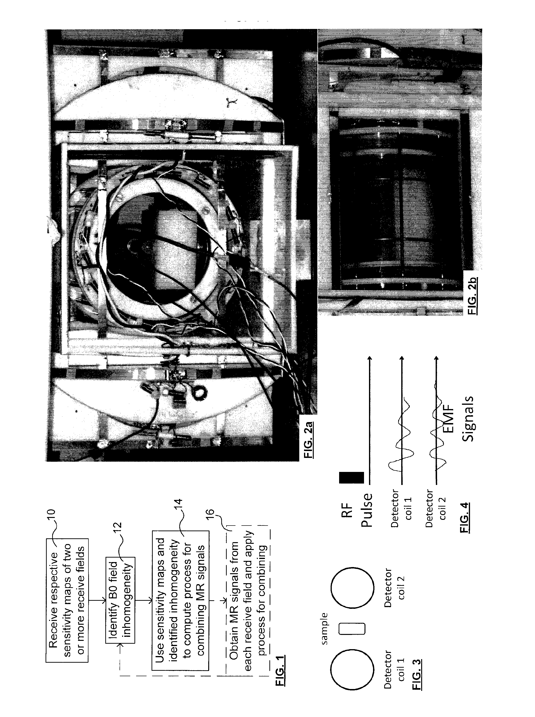
[0081]Experiments were performed on a 0.2 Tesla MRI system (i.e. B0=0.2 T). For this field strength, the resonant RF frequency is around 8.2 MHz. The sample used was a tube of deionized water. Tube size was 100 mm×14 mm (diameter). FIGS. 2a,b shows photographs of the coil array and the sample (front and longitudinal views, respectively). FIG. 3 shows a highly schematic view of the coil array and sample.
[0082]An NMR experiment was performed with two receiver coils. Each receiver coil signal has its own receiver channel. The experiment starts with the transmission of an RF pulse. For this experiment, coil 1 was used at the transmitter. Following the excitation, emfs are received on both receiver coils. FIG. 4 shows the NMR measurement as a pulse sequence diagram. It shows the transmitted RF pulse and the collection of 2 emfs (FIDs) following this pulse. This is a very basic MR procedure in which an RF pulse is generated, and an acquisition window follows. Parallel acqui...
PUM
 Abstract
Description
Claims
Application Information
PatSnap Eureka turns technology decisions into work you can execute. Powered by our Innovation Knowledge Graph, it runs expert workflows across engineering, life sciences, materials and intellectual property. Get your review-ready output in minutes.


