Compact antenna system
- Summary
- Abstract
- Description
- Claims
- Application Information
AI Technical Summary
Benefits of technology
Problems solved by technology
Method used
Image
Examples
Embodiment Construction
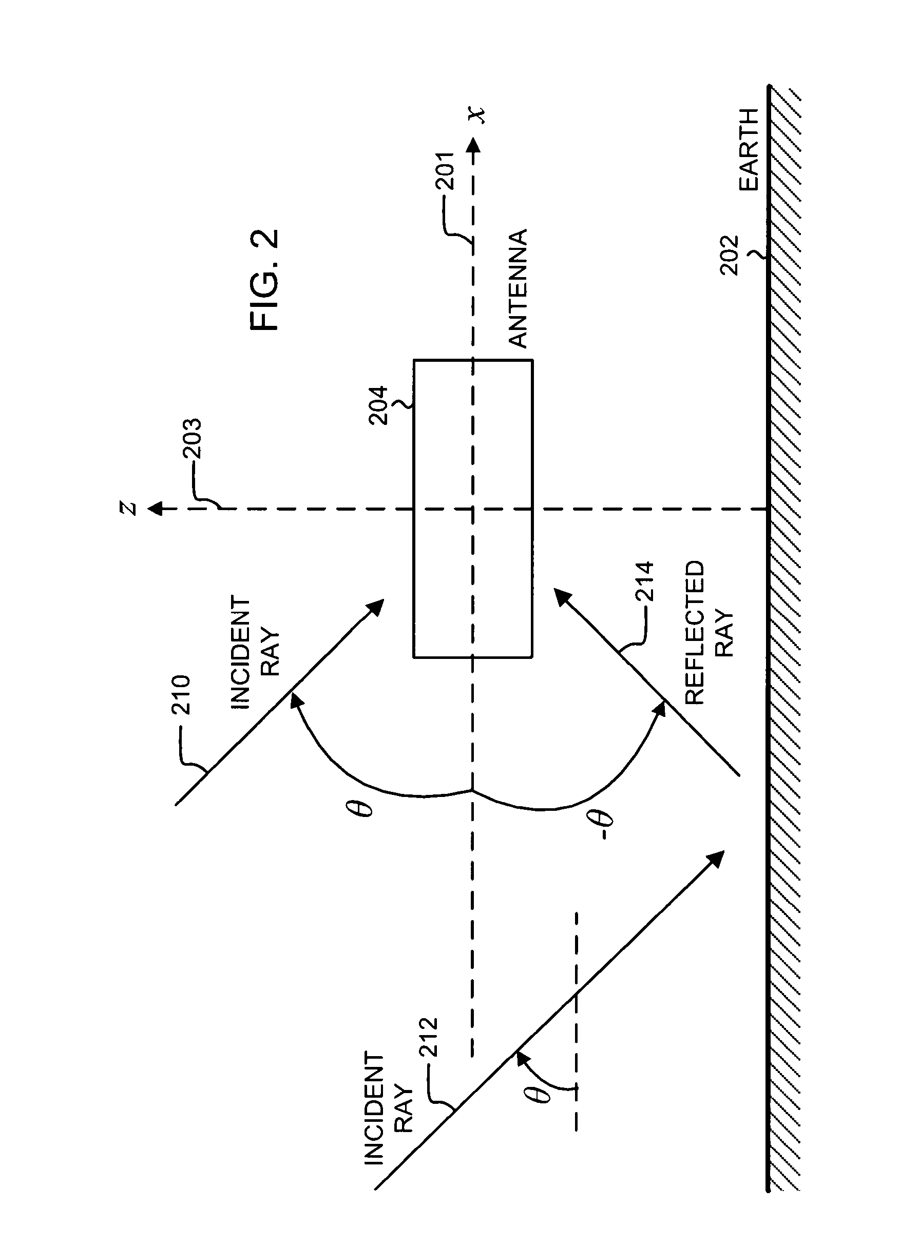
[0044]FIG. 2 shows a schematic of an antenna 204 positioned above the Earth 202. The antenna 204, for example, can be mounted on a surveying pole (not shown) for surveying applications. The plane of the figure is the x-z plane, defined by the x-axis 201 and the z-axis 203. The +y direction points into the plane of the figure. In an open-air environment, the +z (up) direction, also referred to as the zenith, points towards the sky, and the −z (down) direction points towards the Earth. The horizon falls on the x-y plane. Herein, the term Earth includes both land and water environments. To avoid confusion with “electrical” ground, as used in reference to a ground plane, “geographical” ground, as used in reference to land, is not used herein.
[0045]In FIG. 2, electromagnetic waves are represented as rays, incident upon the antenna 204 at an incident angle θ with respect to the x-axis. The horizon corresponds to θ=0 deg. Rays incident from the open sky, such as the ray 210 and the ray 212...
PUM
 Abstract
Description
Claims
Application Information
 - R&D
- Intellectual Property
- Life Sciences
- Materials
- Tech Scout
- Unparalleled Data Quality
- Higher Quality Content
- 60% Fewer Hallucinations
Browse by: Latest US Patents, China's latest patents, Technical Efficacy Thesaurus, Application Domain, Technology Topic, Popular Technical Reports.
© 2025 PatSnap. All rights reserved.Legal|Privacy policy|Modern Slavery Act Transparency Statement|Sitemap|About US| Contact US: help@patsnap.com


