Acoustic transducer and microphone

a transducer and microphone technology, applied in the field of acoustic transducers, can solve the problems of deteriorating sound quality, difficult to maintain sufficient quality, harmonic distortion in the output signal, etc., and achieves wide acoustic range and favorable acoustic characteristics.

Active Publication Date: 2015-03-19
MMI SEMICON CO LTD
View PDF4 Cites 13 Cited by
  • Summary
  • Abstract
  • Description
  • Claims
  • Application Information

AI Technical Summary

Benefits of technology

[0031]According to one or more embodiments of the present invention, it is possible to provide an acoustic transducer that detects sound waves using change in the capacitance between a vibrating electrode and a fix...

Problems solved by technology

However, since charge retention in an electret is easily influenced by a hot atmosphere during microphone manufacturing, there have been cases where maintaining sufficient quality is difficult.
When a microphone attempts to detect a sound having a high sound pressure in the vicinity of the highest compatible sound pressure, harmonic distortion occurs in the output signal, and the sound quality deteriorates.
However, raising the highest compatible sound pressure is difficult in the case of the floating type of fixing technique.
This is because the vibrating electrode is held by electrical attraction acting between the electrodes, and therefore when the sound pressure is comparatively high, the holding force weakens, and there is the risk of the high sound pressure causing misalignment or separation of the vibrating electrode from the fixed electrode and generating distortion in the sound wave detection signal.
However, since the sensitivity to sound pressure is lower in the second detection portion, it is difficult to detect sound waves having a comparatively low sound pressure, and in view of this, the second sensing portion can be favorably used to detect sound waves having a relatively high sound pressure.
In this way, a technique different from the floating type in the first sensing portion is used in the second sensing portion because Applicant found that in the second sensing portion in which the sensitivity is lowered in order to en...

Method used


Image

  • Acoustic transducer and microphone
  • Acoustic transducer and microphone
  • Acoustic transducer and microphone

Examples


embodiment 1

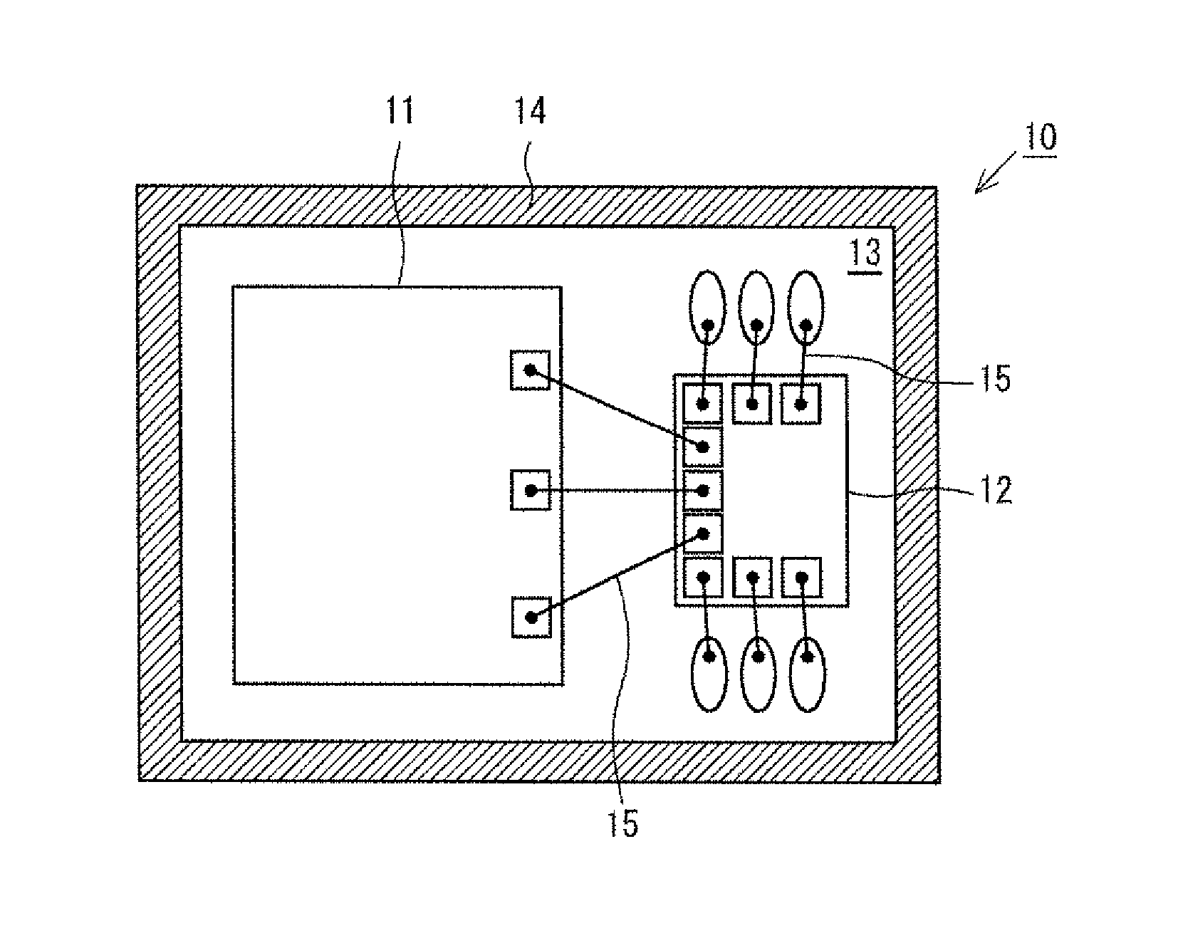
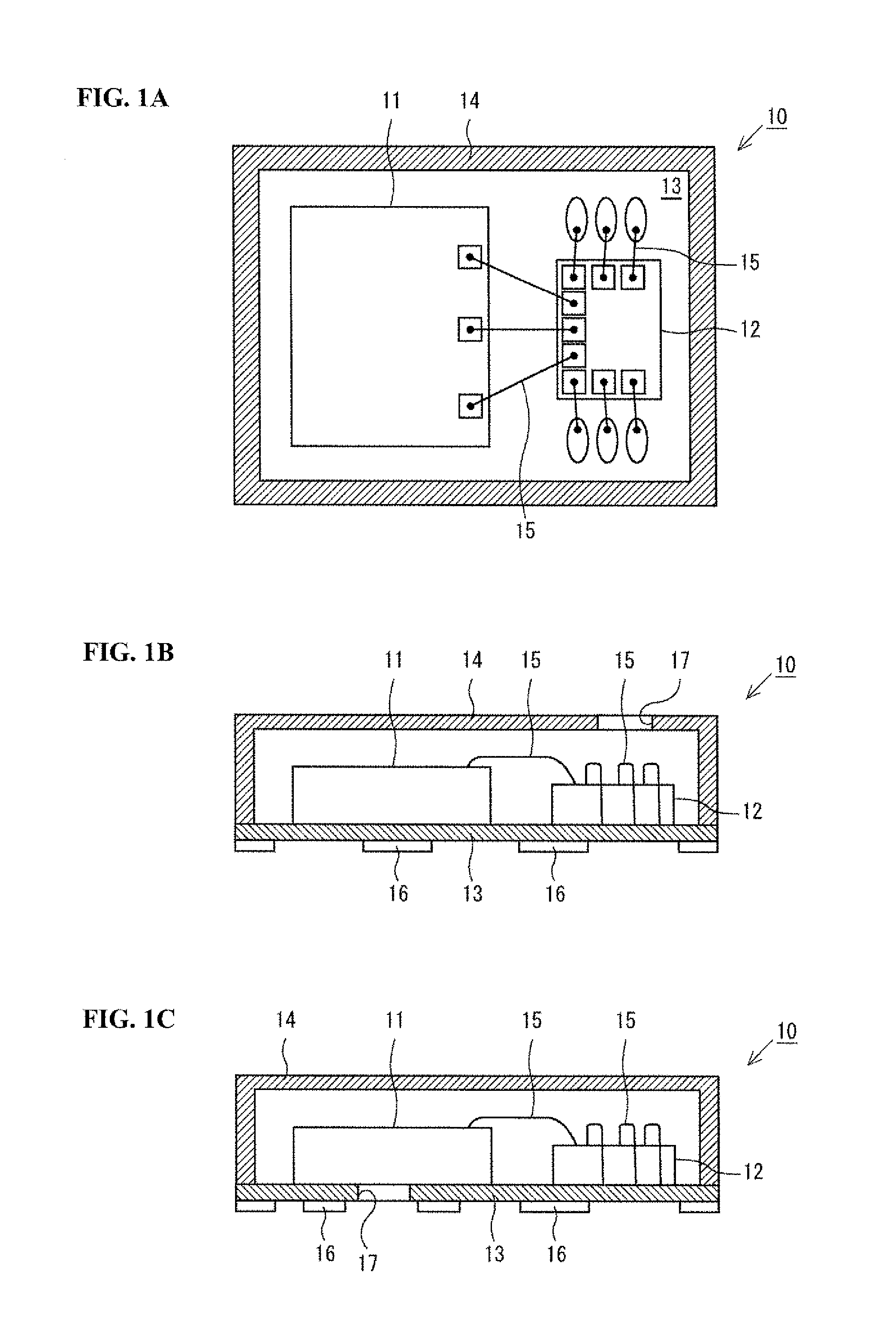
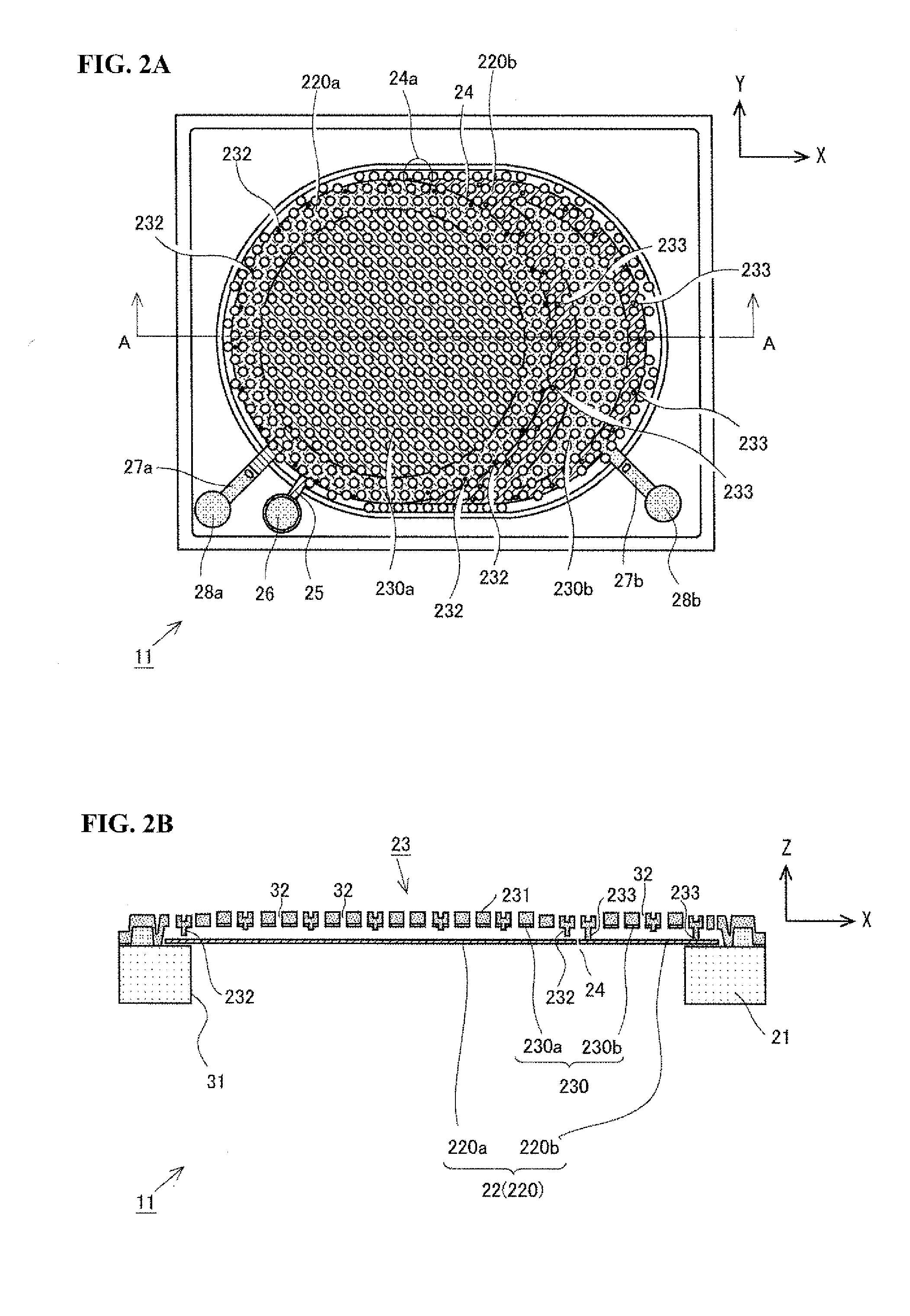
[0042]The following describes a first embodiment of the present invention with reference to FIGS. 1A to 4. FIGS. 1A to 1C show the schematic configuration of a MEMS microphone (referred to hereinafter as simply a “microphone”) 10 according to one or more embodiments of the present invention. FIG. 1A is a top view of the microphone 10, and FIGS. 16 and 1C are front views of the microphone 10. Note that FIG. 1C shows a variation of FIG. 1B. Specifically, as shown in FIGS. 1A to 1C, the microphone 10 is configured so as to include the acoustic transducer 11, an ASIC 12, an interconnect substrate 13, and a casing 14. The acoustic transducer 11 is for detecting sound waves and converting them into an electrical signal (detection signal), and is a MEMS chip manufactured using MEMS technology. Details of the acoustic transducer 11 will be described later. Also, the ASIC 12 is an IC that has a power supply function of supplying power to the acoustic transducer 11 and a signal processing fun...

embodiment 2

[0066]FIGS. 5A and 5B show the schematic configuration of an acoustic transducer 11 according to a second embodiment of the present invention. Note that FIG. 5A is a plan view (XY plan view), and FIG. 5B is a ZX cross-sectional diagram taken along a line A-A in FIG. 5A and viewed in the arrow direction. The acoustic transducer 11 of the second embodiment is different from the acoustic transducer of the first embodiment with respect to the configuration of the vibrating electrode 220 of the vibrating film 22 and the related configurations, and the other configurations are substantially the same. In view of this, the same reference numbers will be used for configurations that are the same, and detailed descriptions will not be given for them.

[0067]In the acoustic transducer 11 of the second embodiment, the first sensing region 220a and the second sensing region 220b of the vibrating electrode 220 are completely isolated by a space occupied by an isolation groove 24b. Specifically, in ...

embodiment 3

[0072]FIGS. 6A and 6B show the schematic configuration of an acoustic transducer 11 according to a third embodiment of the present invention. Note that FIG. 6A is a plan view (XY plan view), and FIG. 6B is a ZX cross-sectional diagram taken along a line A-A in FIG. 6A and viewed in the arrow direction. In the acoustic transducer 11 of the third embodiment, the first sensing region 220a and the second sensing region 220b of the vibrating electrode 220 are completely isolated by the space occupied by the isolation groove 24b likewise to the acoustic transducer of the second embodiment. However, the structural relationship between the fixed film 23 and the in-opening substrate portion 21b is different from the configuration in the second embodiment. In view of this, the same reference numbers will be used for configurations that are similar to those in one or more of the above embodiments, and detailed descriptions will not be given for them.

[0073]In the acoustic transducer 11 of the t...


PUM


Abstract

An acoustic transducer has a vibrating film and a fixed film formed above an opening portion of a substrate, and at least a first sensing portion and a second sensing portion that detect sound waves using change in capacitance between a vibrating electrode provided in the vibrating film and a fixed electrode provided in the fixed film, convert the sound waves into electrical signals, and output the electrical signals. In the first sensing portion and the second sensing portion, the fixed film is used in common, and the vibrating electrode is divided into a first sensing region and a second sensing region that respectively correspond to the first sensing portion and the second sensing portion. In the first sensing portion, a protrusion portion that protrudes toward the vibrating electrode is provided on a region of the fixed film that opposes the first sensing region.

Description

BACKGROUND[0001]1. Field[0002]The present invention relates to an acoustic transducer that detects sound waves using change in the capacitance between a vibrating electrode and a fixed electrode, converts the sound waves into an electrical signal, and outputs the electrical signal.[0003]2. Related Art[0004]Conventionally, an ECM (Electret Condenser Microphone) that employs an electret has been widely used as a small-size microphone for installation in a mobile phone device or the like. However, since charge retention in an electret is easily influenced by a hot atmosphere during microphone manufacturing, there have been cases where maintaining sufficient quality is difficult. This has led to an understanding of the superiority of MEMS microphones, which employ capacitor-type acoustic transducers that detect sound waves and convert them into an electrical signal (detection signal). Note that this acoustic transducer is also called a MEMS microphone since it is manufactured using MEMS...

Claims


Application Information

Patent Timeline
IPC IPC(8): H04R19/04
CPCH04R19/04H04R1/086H04R19/005H04R31/00H04R1/245
Inventor KASAI, TAKASHI
Owner MMI SEMICON CO LTD
Why Eureka
Try Eureka