Method for improving isolation of flow to completed perforated intervals

a technology of perforated intervals and flow isolation, which is applied in the direction of fluid removal, wellbore/well accessories, chemistry apparatus and processes, etc., can solve the problems of difficult construction of sand plugs within horizontal wellbores, time-consuming and expensive use of tubing, and ineffective methods. , to achieve the effect of less surface operating area, less space and less tim

Active Publication Date: 2015-03-26
BAKER HUGHES INC
View PDF3 Cites 46 Cited by
  • Summary
  • Abstract
  • Description
  • Claims
  • Application Information

AI Technical Summary

Benefits of technology

[0016]The use of the well treatment composite described herein renders it unnecessary to separately ship the deformable particulate, diverting agent, viscosifying agent, crosslinking agent and other well treatment additives to a remote location. In addition, less surface operating area is needed on site to perform the well treatment operation since less space is needed for formulating the fluid pill. Further, use of the well treatment composite may save time on the fly by reducing the waiting time normally encountered for fracture closure, settling of a sand plug and forming a sufficient seal.

Problems solved by technology
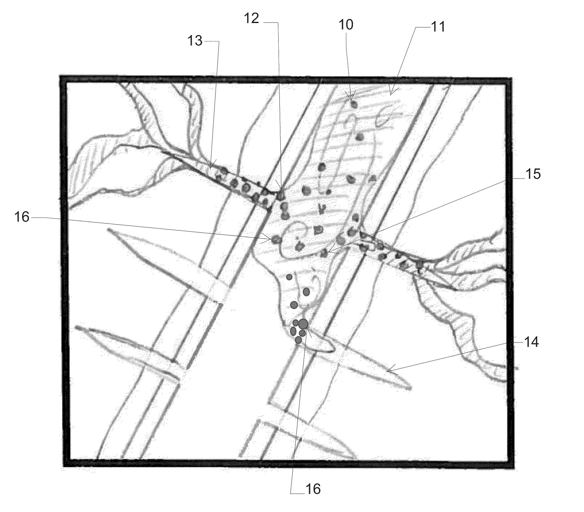
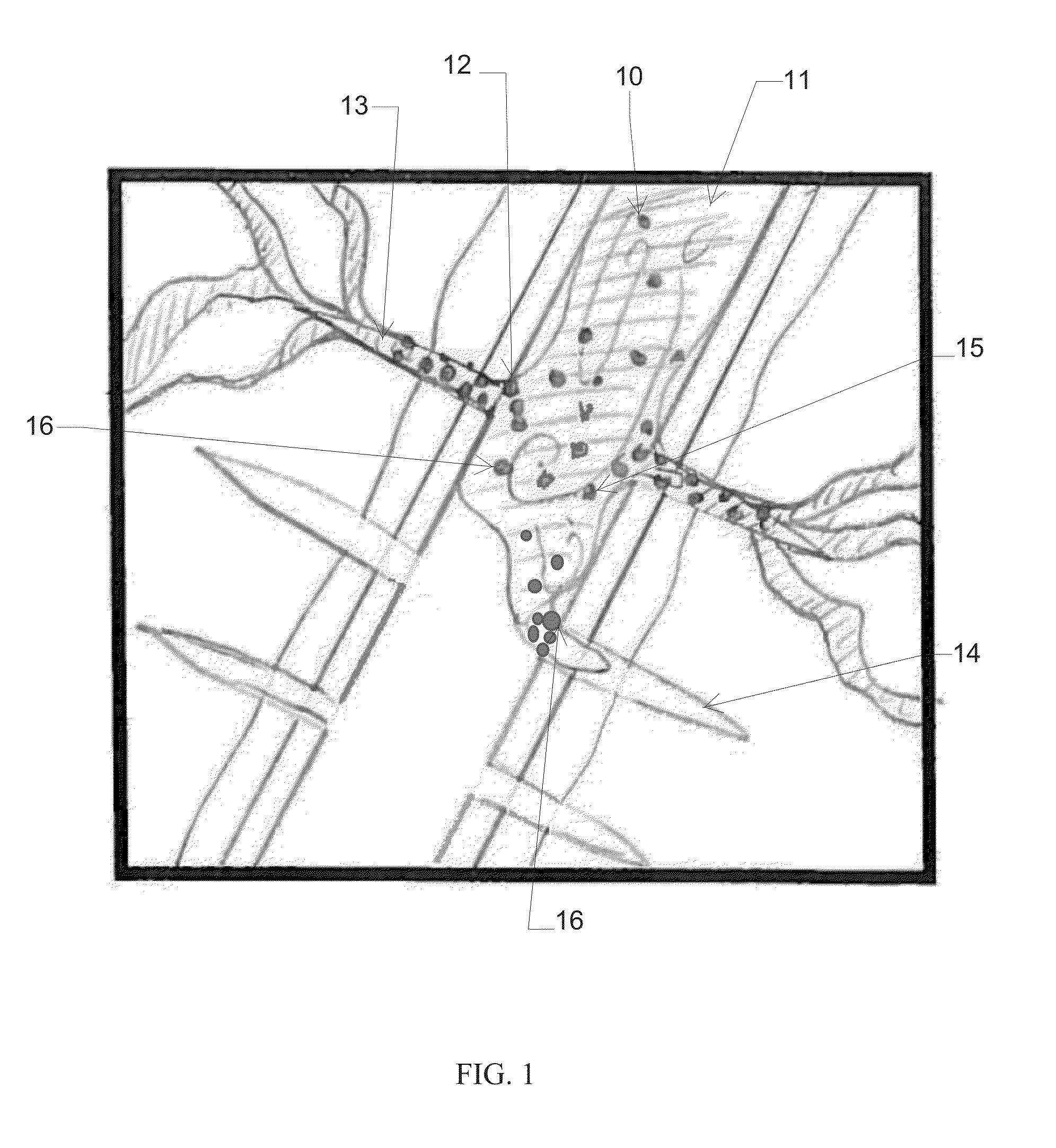
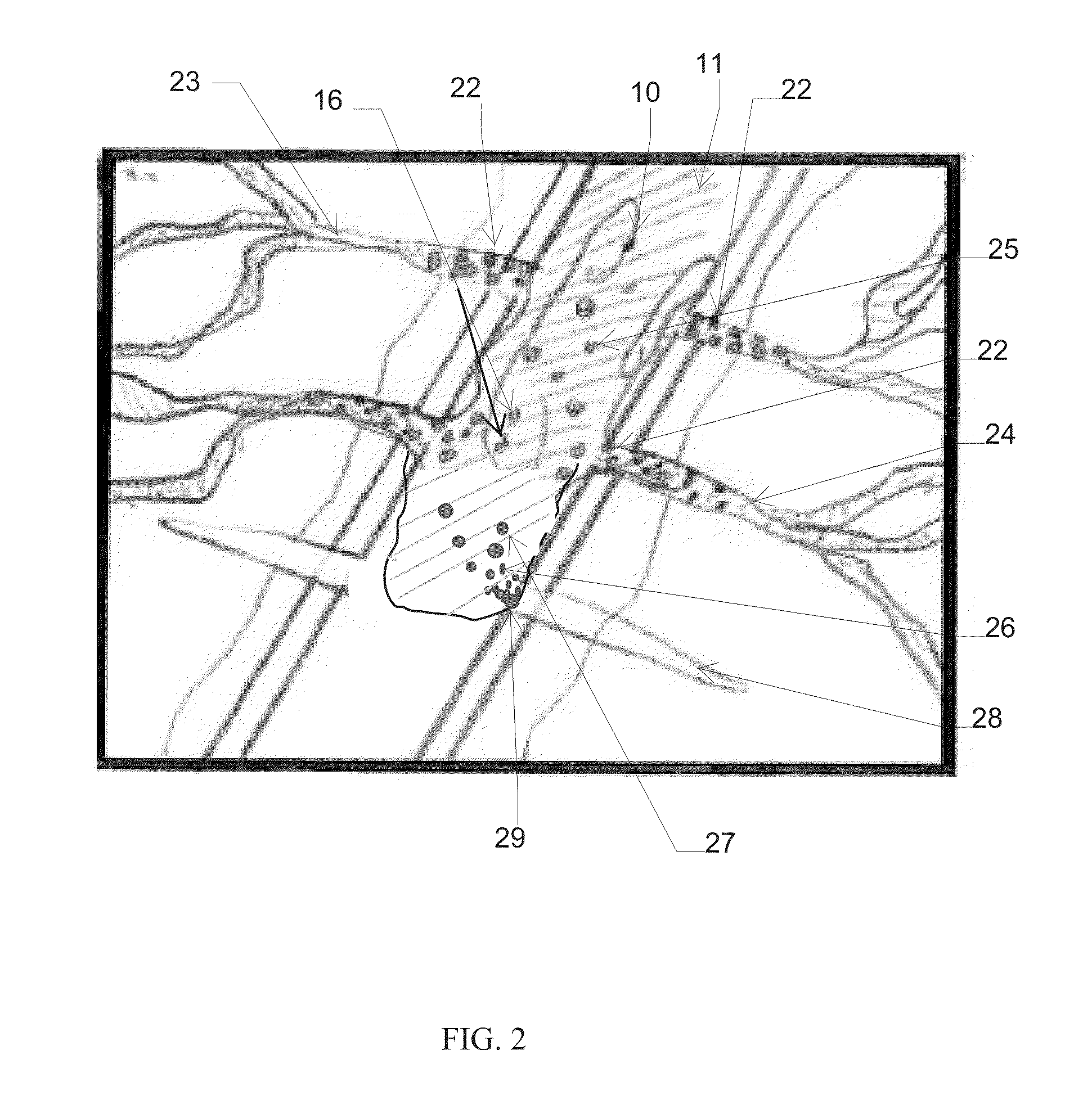
This method, however, is not effective in horizontal wellbores since treatment fluids (necessary for efficient production of hydrocarbons) are displaced by the bridge plug.
While coiled tubing may be used to push and set the bridge plug into a horizontal wellbore, the use of such tubing is time consuming and expensive.
Constructing a sand plug within a horizontal wellbore is difficult since gravitational settling of sand or proppant in the wellbore causes the plug to settle along the bottom of the wellbore which creates a void or channel along the upper side of the wellbore.
Isolation of the treated zone is compromised since the displacement fluid passes down the channel and into the fracture without allowing the sand plug to form.

Method used


Image

  • Method for improving isolation of flow to completed perforated intervals
  • Method for improving isolation of flow to completed perforated intervals
  • Method for improving isolation of flow to completed perforated intervals

Examples


example 1

[0120]A well treating composite having a deformable core particulate and a hardened coating was prepared using, as particulate, LiteProp™ 125, commercially available from Baker Hughes Incorporated, by spraying and drying onto the particulate in sequential steps: (1) 10 lb / Mgal sodium carbonate, (2) 2 lb / gal sodium tetraborate and (3) 40 lb / Mgal guar. The process used a fluid bed coating apparatus having a Glatt coater wherein warm air was blown through the perforated plates below the bed of particulates. The apparatus was operated about at 120° F. to facilitate driving off the water. At times, there was a relatively short period following each spray while the bed was continuing to be fluidized in order to complete drying of a particular stage. A volume of a base fluid (250 ml of 2% KCl) was measured in a beaker and added to a variable speed Waring blender. The desired mass of the untreated particulate and coated particulate was measured using a balance. The Waring blender was turned...

example 2

[0123]Phthalic anhydride (obtained from a commercial supplier) and Sample A (8 g of each) were first diluted in 100 mL deionized water or HCl 15% for 20 hours at 180° F., and then left for 3 hours at room temperature. The mixture was vacuum filtrated with 100 mL water and dried for 24 hours at 160° F. The results are set forth in Table I.

TABLE IMeltingDissolvedRange2,Sample(%)° F.SolventCommercial Phthalic Anhydride6403Deionized waterSample A7.5401Deionized waterSample A, crushed4397-399Deionized waterCommercial Phthalic Anhydride4412HCl 15%Sample A0410HCl 15%Sample A, crushed16415HCl 15%

FTIR and melting point of the recovered undissolved samples showed that the remaining phthalic anhydride had converted into phthalic acid.

example 3

[0124]Samples of Sample A (each 5 g) were diluted in 100 mL of either deionized water (DI) or tap water for (1) 54 hours at 180° F. and (2) 64 hours at 140° F. and then left to cool at room temperature. The solids were vacuum filtrated with 100 mL water and dried for 24 h at 160° F. The results are set forth in Table II.

TABLE II64 hr PERCENT54 hr PERCENTSOLUBILITY @SOLUBILITY @140° F.180° F.taptapwaterDIwaterDI18.513.45.69.3

The FTIR and melting point of the recovered undissolved samples showed that the remaining phthalic anhydride had converted into phthalic acid. Table II illustrates that more phthalic anhydride was converted to phthalic acid at higher temperatures. Sample A was thus more suitable for lower temperature applications.


PUM

PropertyMeasurementUnit
viscosityaaaaaaaaaa
particle sizeaaaaaaaaaa
temperaturesaaaaaaaaaa

Abstract

A method for building a plug in a horizontal wellbore using a fluid pill containing a suspended well treatment composite. The well treatment composite contains a core comprising at least one deformable particulate and at least one dissolvable diverter. At least a portion of the surface of the core is coated with at least one viscosifying polymer and at least one crosslinking agent. The fluid pill is pumped into the wellbore at the end of a fracturing treatment and the fluid pill may be displaced by a displacement fluid. The fluid pill may be diverted to an area of lower permeability by disassociating the dissolvable diverter from the core. The disassociated diverter blocks an area of higher permeability. The sized particle distribution of the diverter is sufficient to at least partially block the penetration of fluid into the high permeability zone. In the lower permeability zone, a thickened gel is formed by the in-situ reaction of the viscosifying polymer and crosslinking. Deformable particulates in the gelled fluid form a bridge plug.

Description

[0001]This application is a continuation-in-part application of U.S. patent application Ser. No. 13 / 302,722, filed on Nov. 22, 2011, herein incorporated by reference. This application is also a continuation-in-part application of U.S. patent application Ser. No. 14 / 512,232 filed on Oct. 10, 2014 which is a continuation-in-part of U.S. patent application Ser. No. 14 / 461,123 filed on Aug. 15, 2014 which is a continuation-in-part application of U.S. patent application Ser. No. 13 / 928,006 filed on Jun. 26, 2013 which claims the benefit of U.S. provisional application Ser. No. 61 / 664,640 filed on Jun. 26, 2012, all of which are herein incorporated by reference.FIELD OF THE DISCLOSURE[0002]The present disclosure relates to an improved method for building a fluid-impermeable plug in a horizontal wellbore with a fluid pill containing a well treatment composite comprising a core of a dissolvable diverter and a deformable particulate and a viscosifying polymer and crosslinking agent coated on...

Claims


Application Information

Patent Timeline
Patent Type & Authority Applications(United States)
IPC IPC(8): C09K8/42E21B43/267C09K8/80E21B33/13
CPCC09K8/426C09K8/805E21B43/267E21B33/13C09K8/512C09K8/516C09K8/62C09K2208/18E21B21/003E21B33/134E21B43/305
Inventor BRANNON, HAROLD DEANHUDSON, HAROLD GENENELSON, SCOTT GREGORYGUPTA, D.V. SATYANARAYANA
Owner BAKER HUGHES INC
Why Eureka
Try Eureka