Non-welded battery module

Inactive Publication Date: 2015-03-26
LIEW CHUNG PENG
View PDF10 Cites 19 Cited by
  • Summary
  • Abstract
  • Description
  • Claims
  • Application Information

AI Technical Summary

Benefits of technology

[0008]Another advantage of the present invention is to provide the possibility reusing and recycling battery cell as there involves no spot welding mark on the battery cell.
[0009]It is another object of the present invention to provide a battery pack including whereby the structural stability of the battery pack is improved.
[0010]The present invention resides in a combination of an electric battery pack and a apparatus for making an electrical connection to the battery without involving the spot welding process. The apparatus includes conductive members, nickel or other conductive material plated copper sheet secured to a conductive battery terminal exposed at an external surface of the battery and a pressure plate connected to an electrically insulating material namely silicone rubber sheet and wherein the conductive terminal namely negative and positive terminal are encapsulated in the said electrically insulating material which is substantially self-sealing when compressed.
[0011]Preferably, the encapsulant is contained pressure on said external surface of the battery cell so as to enclose said terminal and said conductiv

Problems solved by technology

Compare to the battery pack use in the computer notebook or similar size battery pack, the battery pack use in EV is much bigger, and therefore the process to make the pack is much complicated and costly if any defect were to occur during the assembly process.
The substantial amount of heat generated from battery cell that increases temperature in the battery pack is a common problem in all Lithium batteries, therefore exists a pressing need to disperse the heat out from the cell.
However, the conventional methods are not without

Method used


Image

  • Non-welded battery module
  • Non-welded battery module
  • Non-welded battery module

Examples


Embodiment Construction

[0027]The preferred embodiments of the present invention will be described in detail with reference to the accompanying drawings. It should be noted, however, that the scope of the present invention is not limited by the illustrated embodiments.

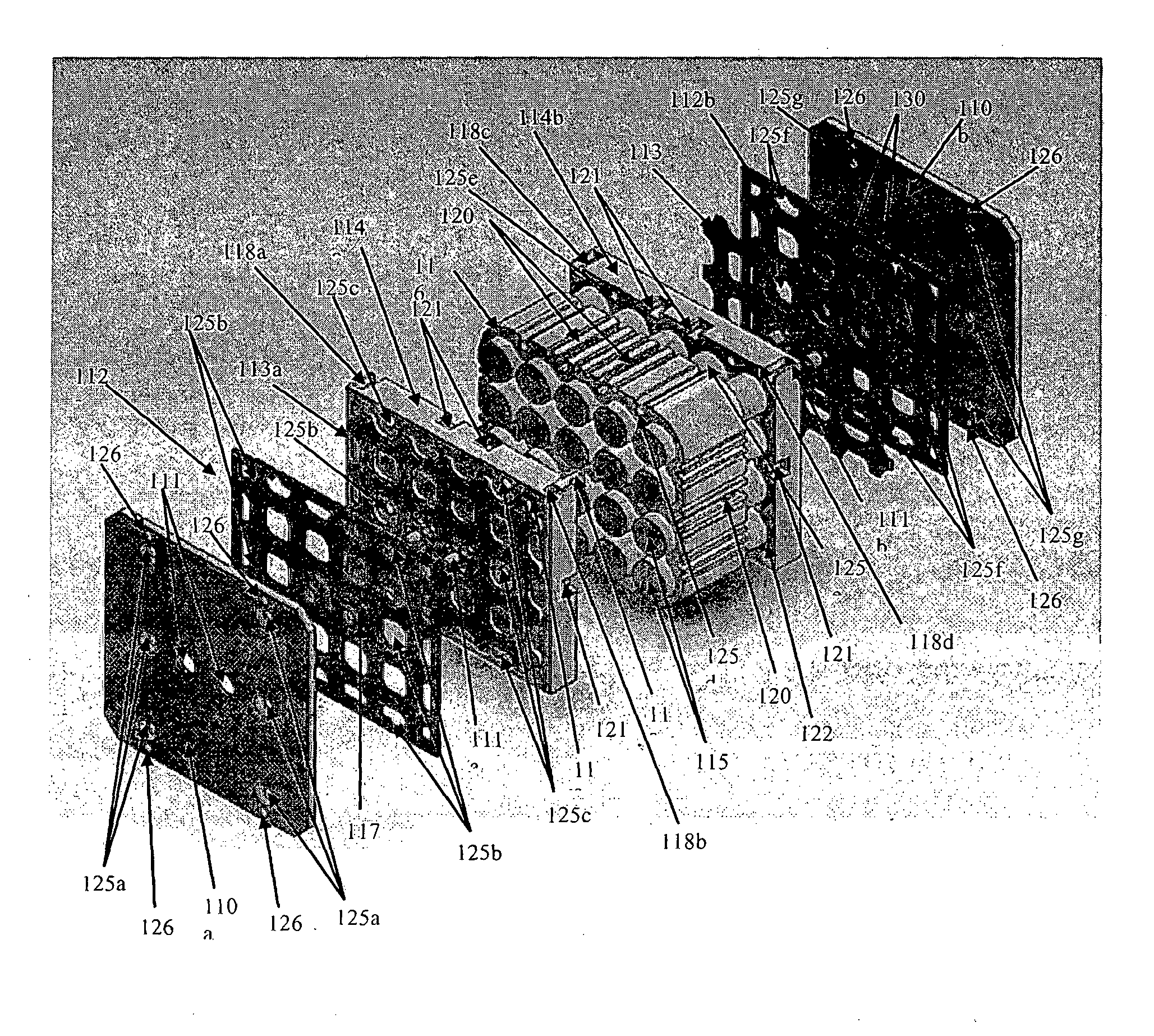
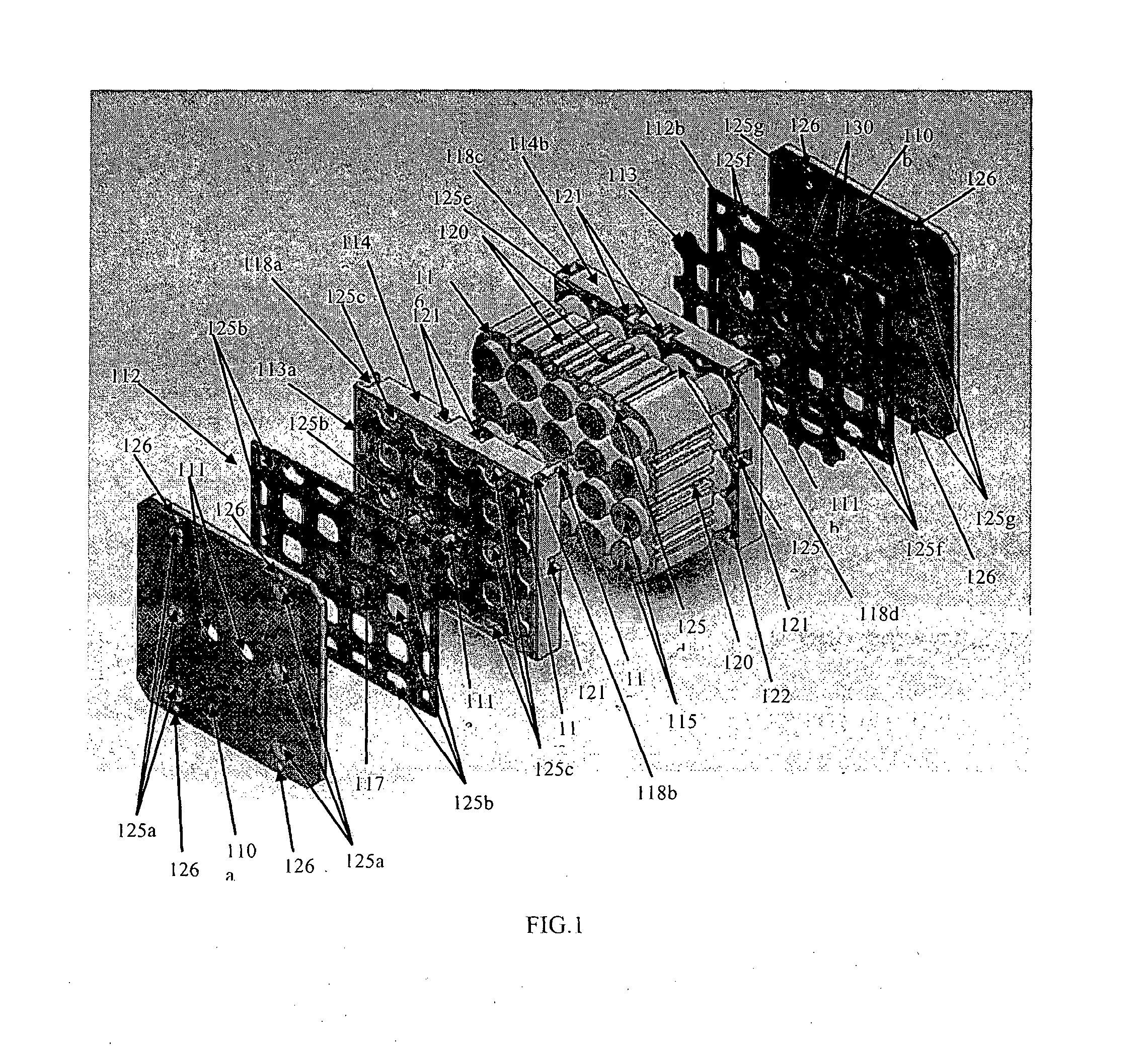
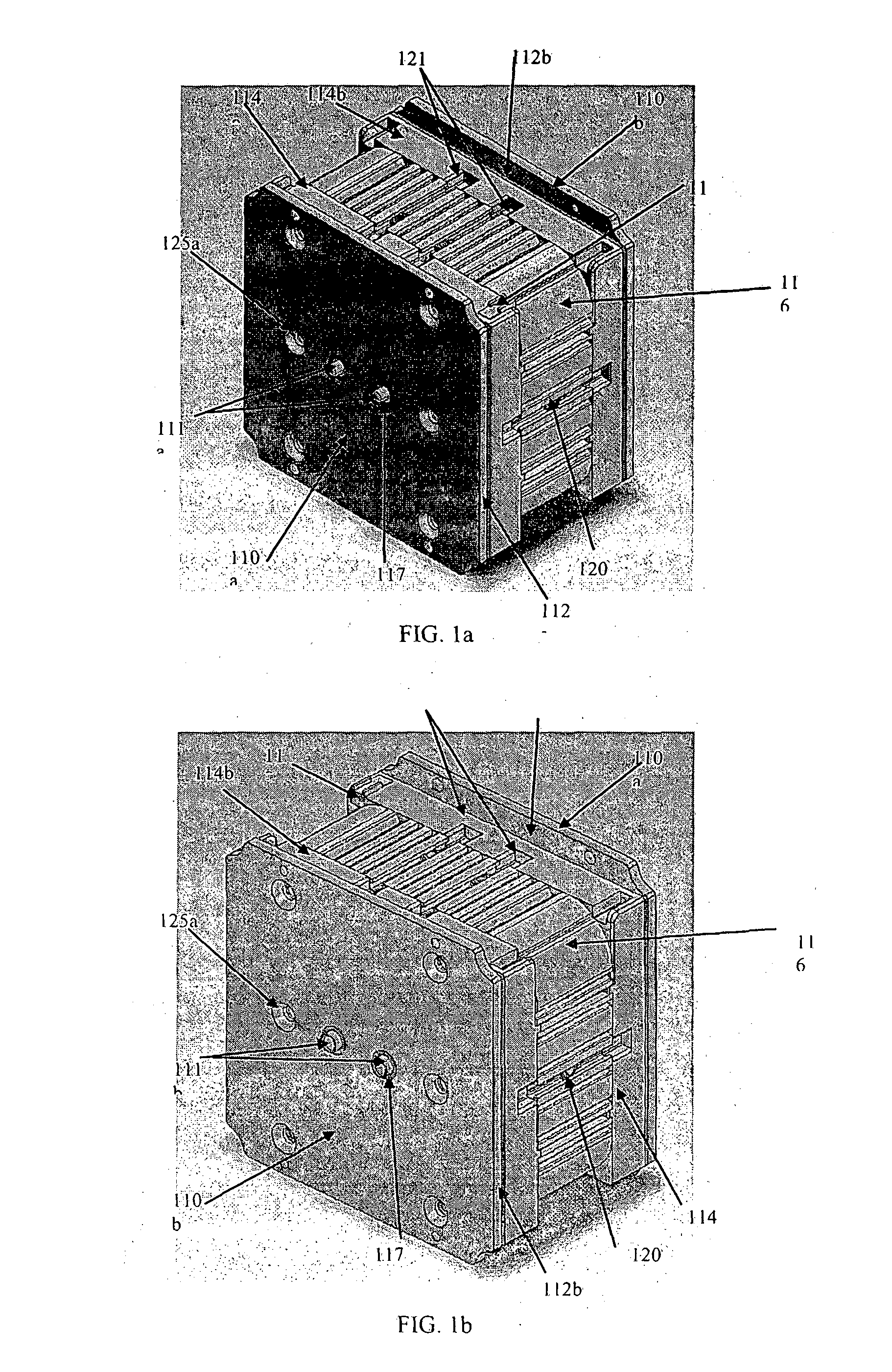
[0028]Referring to FIG. 1 is the exploded view the overall battery pack assembly. First is the negative pressure plate (110a), followed by the negative silicone rubber pressure sheet (112a) and negative nickel or other conductive material plated copper sheet (113a) that is connected with the negative terminal (111a). The negative battery cell holder (114a) that holds the battery cells (115) through the Aluminum or other material like plastic, but not limited to, heat sink casing (116) can be seen. On the other end of the battery cells (115) is the positive side of the terminal that is connected to the positive battery cell holder (114b) followed by the positive nickel or other conductive material plated copper sheet (113b) that is connected w...


PUM


Abstract

This invention relates to an improvement in battery packs. The present invention resides in a combination of an electric battery pack and a apparatus for making an electrical connection to the battery without involving the spot welding process. The present assembly method enables terminal blocks containing multiple battery packs joint in series having a “U-turn” configuration without external electrical connection. Any two battery packs are firmly locked together through the pressure plates (200) without being electrically connected together. The present embodiment uses two separate nickel or other conductive material plated copper sheets (113a or 113b) that are embedded between the battery cell holder (114a, 114b) and the silicone rubber pressure sheet (112a, 112b). The first end portion block of battery packs supported by an end pressure plate (300) can be connected together to the second end portion of the block battery packs by using a modified nickel or other conductive material plated copper sheet (113) that enable the two battery packs to be connected internally, thus, making the “U-turn” configuration possible. This method is one of the most cost efficient ways to connect internally, to avoid using any external wires or circuits, which eventually maintain the internal resistance of each of the battery packs.

Description

BACKGROUND OF THE INVENTION[0001]The battery is the most important part in the Electric Vehicle (EV). The most promising battery technology today for the EV industry is Lithium Battery, especially the cylindrical Li-Ion (Lithium Ion) cell. Compare to the battery pack use in the computer notebook or similar size battery pack, the battery pack use in EV is much bigger, and therefore the process to make the pack is much complicated and costly if any defect were to occur during the assembly process. The definition of battery end of life in EV battery pack is about 70% energy left compare to the new battery pack. The battery cells from this end of life battery pack are still useful in other application like power grid energy buffer or solar energy storage where space is no longer a concern compared to in the EV. The substantial amount of heat generated from battery cell that increases temperature in the battery pack is a common problem in all Lithium batteries, therefore exists a pressin...

Claims


Application Information

Patent Timeline
IPC IPC(8): H01M2/10H01M2/20H01M50/213H01M50/262H01M50/51H01M50/517H01M50/522H01M50/526
CPCH01M2/1083H01M2220/20H01M2/206H01M10/52H01M10/54Y02W30/84Y02E60/10Y02P70/50H01M50/522H01M50/526H01M50/213H01M50/517H01M50/51H01M50/262
Inventor LIEW, CHUNG PENG
Owner LIEW CHUNG PENG
Why Eureka
Try Eureka