Electrical actuator for vehicle transmission system
a technology of electric actuator and transmission system, which is applied in the direction of mechanical actuated clutches, electric devices, dc motor rotation control, etc., can solve the problems of cost and bulkyness
- Summary
- Abstract
- Description
- Claims
- Application Information
AI Technical Summary
Benefits of technology
Problems solved by technology
Method used
Image
Examples
Embodiment Construction
)
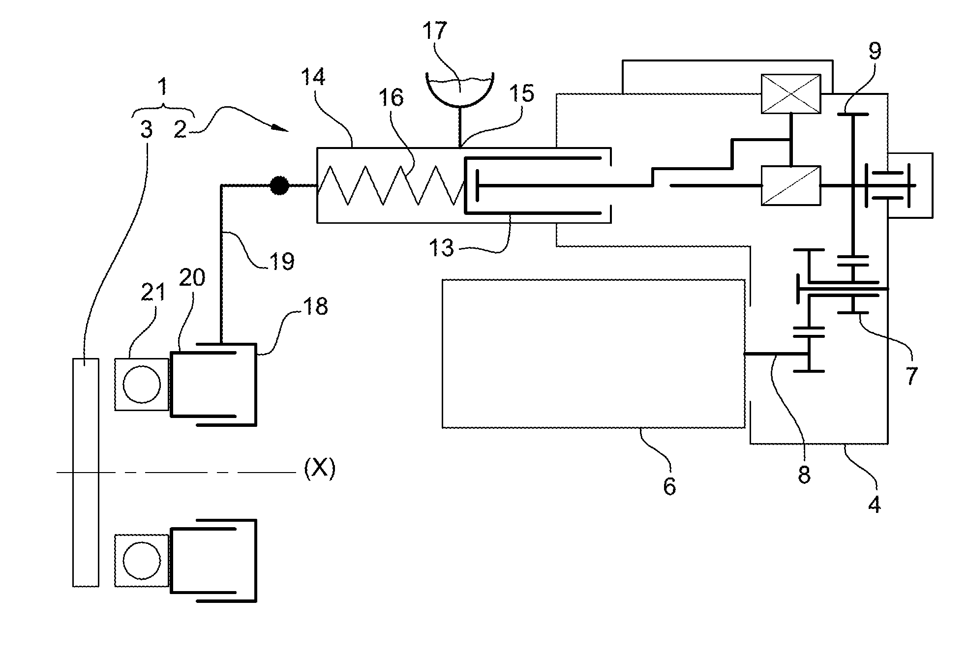
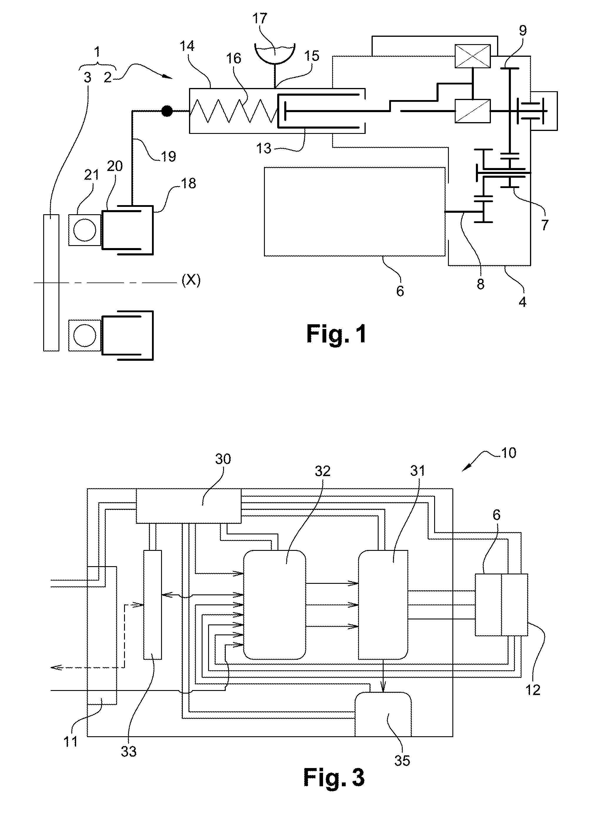
[0123]FIG. 1 depicts an assemblage 1 comprising an actuator 2 interacting with a transmission system 3. In the example of FIG. 1, transmission system 3 is a single clutch.
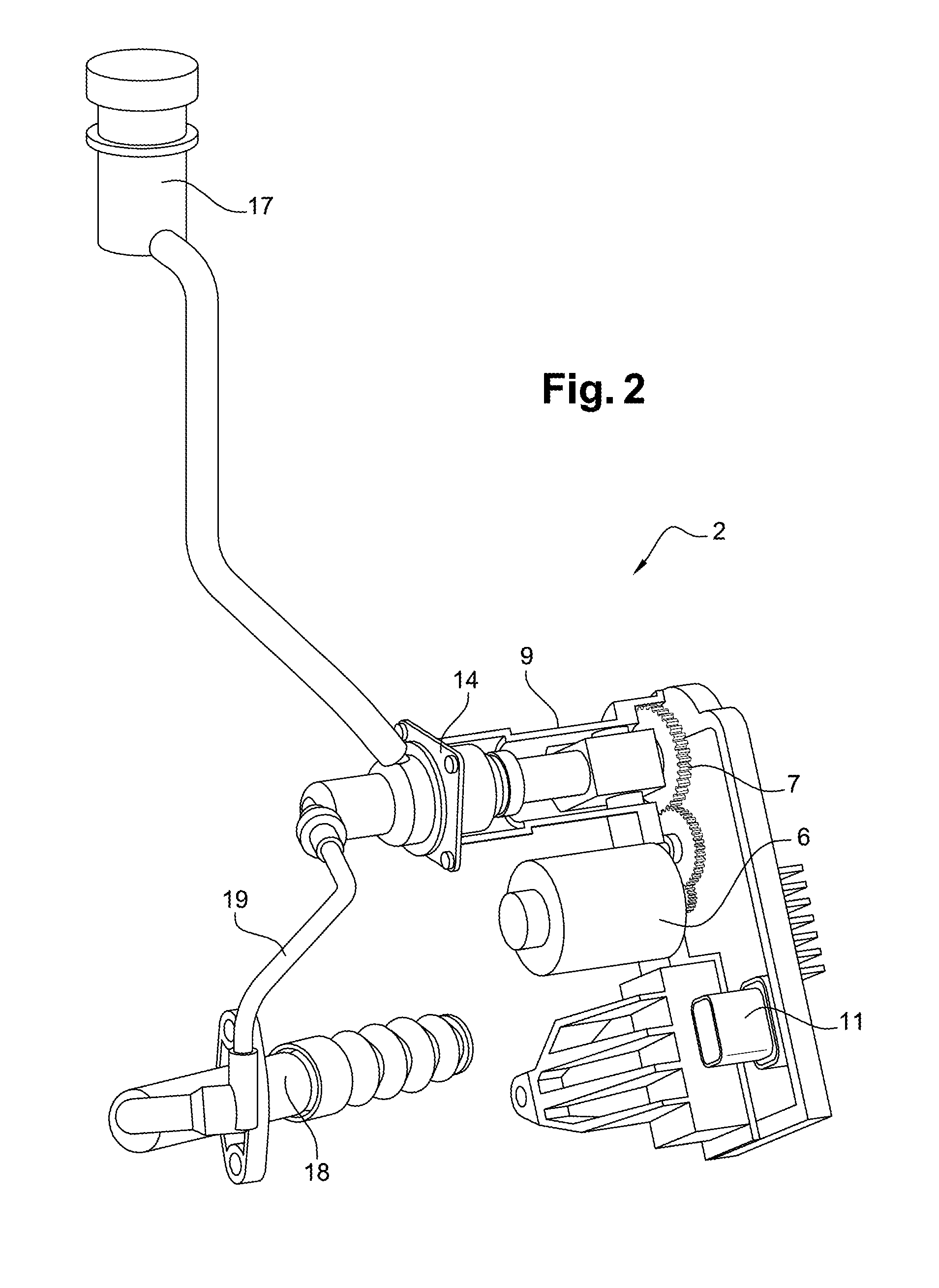
[0124]In this example, actuator 2 comprises a housing 4 coacting with the crankcase of an electrical machine 6. The housing can be mounted on the engine / propulsion assembly, or on the chassis, of a vehicle.
[0125]Housing 4 can receive a reduction gearbox 7 rotationally driven by output shaft 8 of electrical machine 6, and a rotary / linear motion transformation system 9. Reduction gearbox 7 here has a fixed transmission ratio. Reduction gearbox 7 can comprise one or two reduction stages. In the example considered, the value of the reduction gearbox transmission ratio is determined as a function of the maximum power output applied by transmission system 3 to actuator 2, in order to reduce the electromagnetic torque that must be applied to the rotor of electrical machine 6 when it holds transmission system 3 in a given...
PUM
 Abstract
Description
Claims
Application Information
 - R&D
- Intellectual Property
- Life Sciences
- Materials
- Tech Scout
- Unparalleled Data Quality
- Higher Quality Content
- 60% Fewer Hallucinations
Browse by: Latest US Patents, China's latest patents, Technical Efficacy Thesaurus, Application Domain, Technology Topic, Popular Technical Reports.
© 2025 PatSnap. All rights reserved.Legal|Privacy policy|Modern Slavery Act Transparency Statement|Sitemap|About US| Contact US: help@patsnap.com


