Selective growth of a work-function metal in a replacement metal gate of a semiconductor device

a technology of work-function metal and replacement metal, which is applied in the direction of solid-state devices, transistors, electric devices, etc., can solve the problems of non-uniform or catastrophic metal recesses, difficult metal chamfering, and undesirable approaches, so as to reduce the risk of mask materials filling into each gate recess, improve the filling of metal materials, and reduce the gate resistance in the device

Inactive Publication Date: 2015-04-23
GLOBALFOUNDRIES INC
View PDF0 Cites 35 Cited by
  • Summary
  • Abstract
  • Description
  • Claims
  • Application Information

AI Technical Summary

Benefits of technology

[0009]In general, approaches for forming a replacement metal gate (RMG) of a semiconductor device, are disclosed. Specifically, provided is a p-channel field effect transistor (p-FET) and an n-channel field effect transistor (n-FET) formed over a substrate, the p-FET and the n-FET each having a recess formed therein, a high-k layer, a barrier layer, and an optional metal layer formed within each recess, a work-function metal (WFM) selectively grown within the recess of the n-FET, and a metal material (e.g., Tungsten) formed within each recess. By performing a chamfer of the high-k layer, barrier layer, and the metal layer earlier in the process, the risk of mask materials filling into each gate recess is reduced. Furthermore, the selective WFM growth (e.g., of a single-element metal as opposed to a metal compound) improves fill-in of the metal material, which lowers gate resistance in the device.
[0010]One aspect of the present invention includes method for forming a replacement metal gate (RMG) of a semiconductor device, the method comprising: providing a set of field effect transistors (FET) formed over a substrate, each of the set of FETs having a recess formed therein; forming a high-k layer over the semiconductor device and within each recess; forming a barrier layer over the high-k layer; forming an organic dielectric layer (ODL) within each recess; recessing the ODL to a desired height within each recess; removing the high-k layer and the barrier layer from atop the semiconductor device selective to the ODL within each reces

Problems solved by technology

However, tight PC dimensions make metal chamfering challenging.
In another approach, shown in FIG. 2, a pinch-off of TiN 220 causes a seam/void 230 to form in recess 210, which results in a non-uniform or catastrophic metal recess.

Method used


Image

  • Selective growth of a work-function metal in a replacement metal gate of a semiconductor device
  • Selective growth of a work-function metal in a replacement metal gate of a semiconductor device
  • Selective growth of a work-function metal in a replacement metal gate of a semiconductor device

Examples


Embodiment Construction

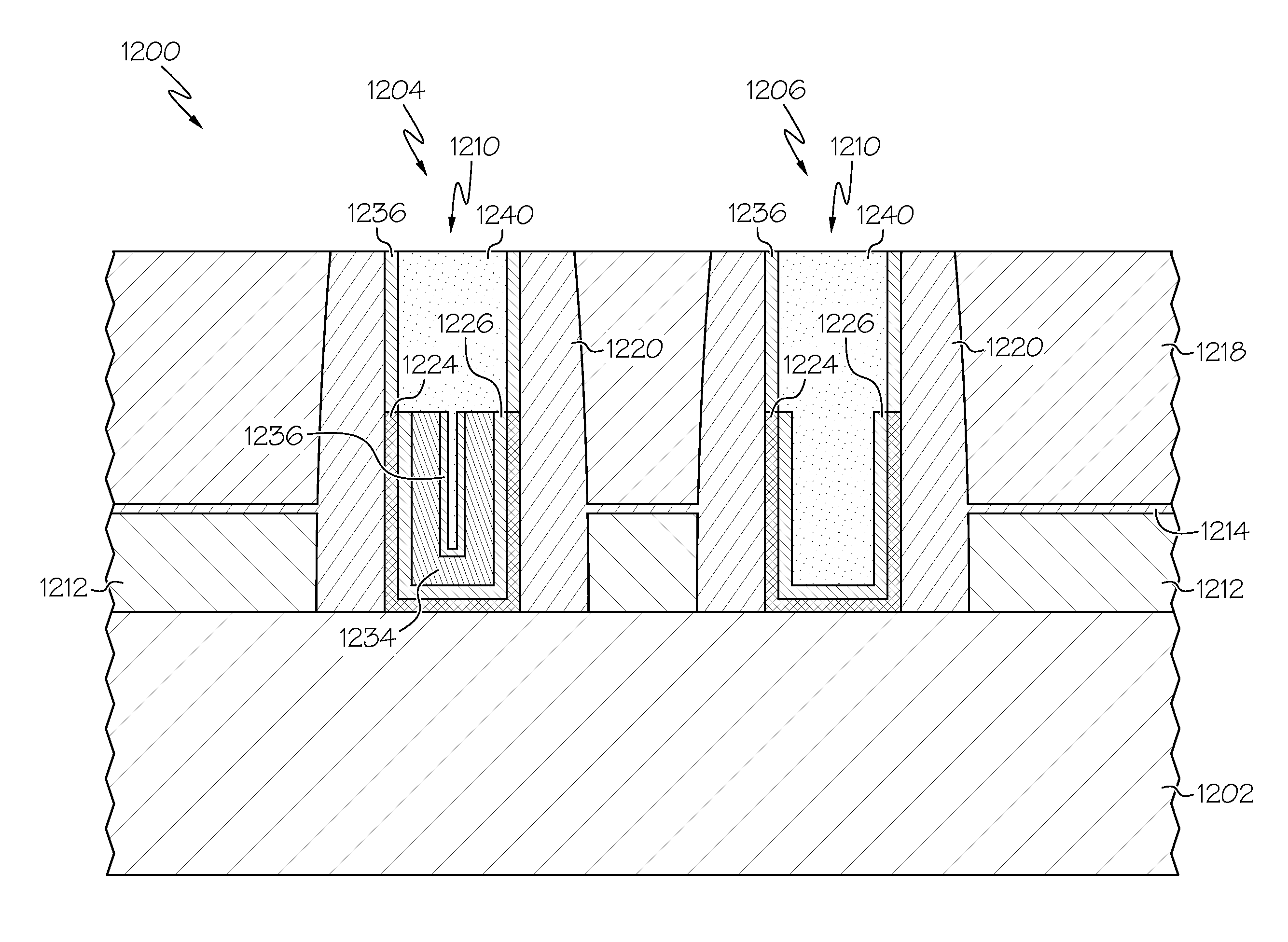
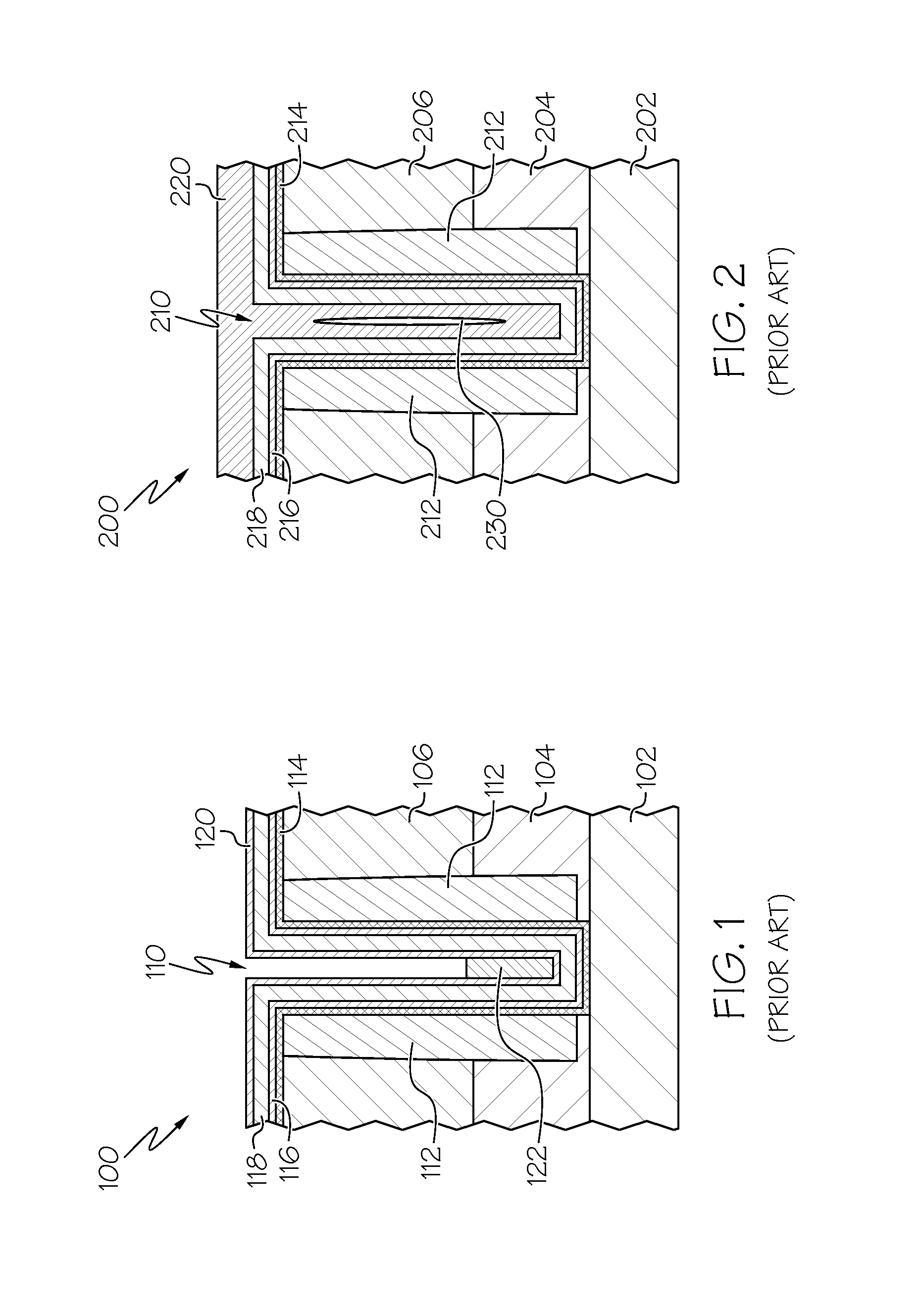
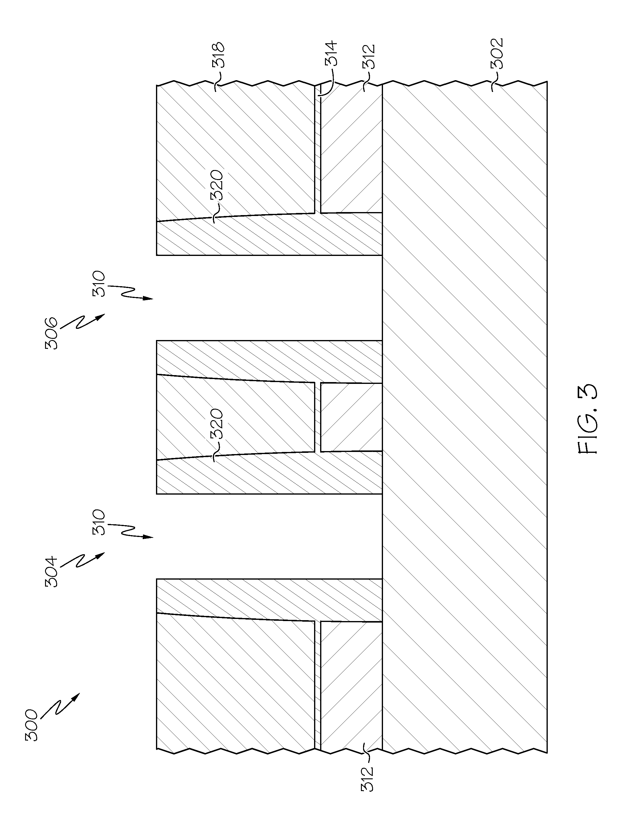
[0028]Exemplary embodiments will now be described more fully herein with reference to the accompanying drawings, in which exemplary embodiments are shown. It will be appreciated that this disclosure may be embodied in many different forms and should not be construed as limited to the exemplary embodiments set forth herein. Rather, these exemplary embodiments are provided so that this disclosure will be thorough and complete and will fully convey the scope of this disclosure to those skilled in the art. The terminology used herein is for the purpose of describing particular embodiments only and is not intended to be limiting of this disclosure. For example, as used herein, the singular forms “a”, “an”, and “the” are intended to include the plural forms as well, unless the context clearly indicates otherwise. Furthermore, the use of the terms “a”, “an”, etc., do not denote a limitation of quantity, but rather denote the presence of at least one of the referenced items. It will be furt...


PUM


Abstract

Approaches for forming a replacement metal gate (RMG) of a semiconductor device, are disclosed. Specifically provided is a p-channel field effect transistor (p-FET) and an n-channel field effect transistor (n-FET) formed over a substrate, the p-FET and the n-FET each having a recess formed therein, a high-k layer and a barrier layer formed within each recess, a work-function metal (WFM) selectively grown within the recess of the n-FET, wherein the high-k layer, barrier layer, and WFM are each recessed to a desired height within the recesses, and a metal material (e.g., Tungsten) formed within each recess. By providing a WFM chamfer earlier in the process, the risk of mask materials filling into each gate recess is reduced. Furthermore, the selective WFM growth improves fill-in of the metal material, which lowers gate resistance in the device.

Description

BACKGROUND[0001]1. Technical Field[0002]This invention relates generally to the field of semiconductors and, more particularly, to forming a replacement metal gate (RMG) of a semiconductor device.[0003]2. Related Art[0004]Metal-oxide-semiconductor (MOS) transistors using polysilicon gate electrodes are known. Polysilicon material is able to tolerate high temperature processing better than most metals, so that polysilicon can be annealed at high temperatures along with source and drain regions. In addition, polysilicon blocks ion implantation of doped atoms into a channel region, facilitating the formation of self-aligned source and drain structures after gate patterning is completed.[0005]The high resistivities of polysilicon materials, as compared to most metal materials, result in polysilicon gate electrodes that operate at much slower speeds than gates made of metallic materials. One way of compensating for the higher resistance of polysilicon materials is to perform extensive si...

Claims


Application Information

Patent Timeline
IPC IPC(8): H01L21/28H01L29/49H01L27/092H01L29/51
CPCH01L21/28008H01L27/092H01L29/4966H01L29/517H01L21/823842H01L21/823821H01L21/31144H01L21/32139H01L27/0922H01L27/0924
Inventor CAI, XIUYUKIM, HOONZHANG, XUNYUAN
Owner GLOBALFOUNDRIES INC
Why Eureka
Try Eureka