Method of making a dental prosthesis

a dental restoration and prosthesis technology, applied in the field of making a dental restoration or prosthesis, can solve the problems of insufficient treatment and cavitation

Active Publication Date: 2015-04-23
B & D DENTAL
View PDF9 Cites 26 Cited by
  • Summary
  • Abstract
  • Description
  • Claims
  • Application Information

AI Technical Summary

Benefits of technology

[0021]It has been recognized by the present inventors that it would be advantageous to develop a dental prosthesis, such as dental crown or bridge restoration, and method for making the dental prosthesis with a second material filling an open space or pocket in a precursor prosthesis of a first restorative material.
[0026]In addition, it has been recognized by the present inventors that there is a need for a dental prosthesis, such as a crown or bridge, to 1) release caries inhibiting bioactive agents for an extended period of time from a mass or bulk that sustains a continual release of ions, instead of a short period of time, directly towards the unrestored adjacent tooth, and 2) have a high flexural strength that comes ultimately from the first material in a stress-bearing area over at least 100 Mpa, preferably over 150 Mpa as in the first material being a glass polymer crown, preferably over 200 Mpa as in the first material being a nano ceramic crown, preferably over 400 Mpa as in the first material being a glass ceramic crown, preferably over 1,000 Mpa as in the first material being a zirconia crown, and 3) can withstand high temperature, preferably over 300° C., heat treatment in post processing for strengthening purposes.
[0027]The present invention provides a method for making a dental prosthesis or restoration, such as a dental crown or bridge, that is capable of inhibiting caries so that the adjacent natural teeth can get the benefit of reduced caries incidents. More specifically, the present invention presents a method of making a dental crown having a caries inhibiting material applied to the open space created on or around at least one of the mesial and distal contact areas so that the natural teeth contacting the crown can achieve a reduced occurrence of dental caries.
[0034]CIMs and FRRMs cannot be used alone to make a crown due to the weak nature of the material. The main limitation of the glass ionomer cements as one form of FRRM is their relative lack of strength and low resistance to abrasion and wear. Conventional low-viscosity glass ionomer cements have low flexural strength (with flexural strength usually lower than 80 Mpa) but high modulus of elasticity, and are therefore very brittle and prone to bulk fracture. Some glass cements are arguably stronger than conventional materials but their fracture resistance remains low. The resin-modified glass-ionomer (RMGI) materials as another form of FRRM have been shown to have significantly higher flexural and tensile strengths and lower modulus of elasticity than the conventional materials. They are therefore more fracture-resistant but their wear resistance is not adequate. In addition, their strength properties are still far inferior (around 100 Mpa) to those of composite-resins, and so should not be subject to undue occlusal load unless they are well supported by surrounding tooth structure. For example, the observed mechanical property degradation of one of the leading brand RMGIs in both neutral and acidic conditions can be attributed to the permeability and porosity of glass ionomers. (J. W. Nicholson and B. Czarnecka, “The release of ions by compomers under neutral and acidic conditions,” Journal of Oral Rehabilitation, vol. 31, no. 7, pp. 665-670, 2004). Being permeable, glass ionomers readily uptake storage media (A. J. Preston, S. M. Higham, E. A. Agalamanyi, and L. H. Mair, “Fluoride recharge of aesthetic dental materials,” Journal of Oral Rehabilitation, vol. 26, no. 12, pp. 936-940, 1999). While this enhances fluoride release and fluoride recharge (X. Xu and J. O. Burgess, “Compressive strength, fluoride release and recharge of fluoride-releasing materials,” Biomaterials, vol. 24, no. 14, pp. 2451-2461, 2003), it can also cause breakdown of the non-silanized glass fillers within glass ionomers and produce a reduction in mechanical properties. This degradation, as well as the absolute values of glass ionomer physical properties, limits the use of glass ionomers in load bearing restorations.

Problems solved by technology

When the enamel and dentin no longer have adequate structure to maintain their mineral framework, cavitation takes place and remineralization is an insufficient treatment.

Method used


Image

  • Method of making a dental prosthesis
  • Method of making a dental prosthesis
  • Method of making a dental prosthesis

Examples


example 1

Full Contour Zirconia, Manual Creation of the Open Space

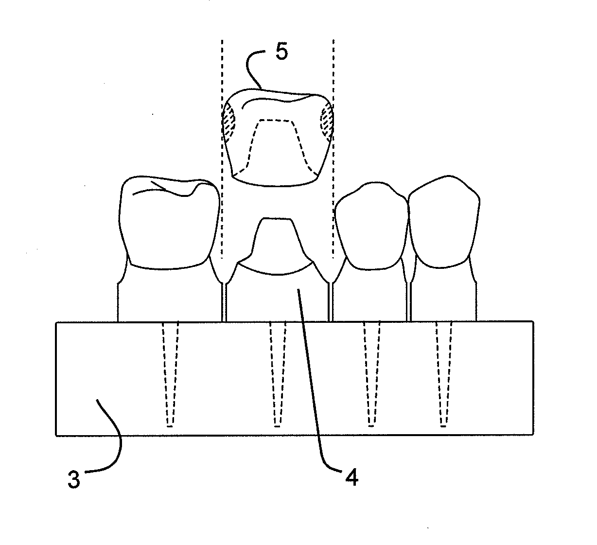
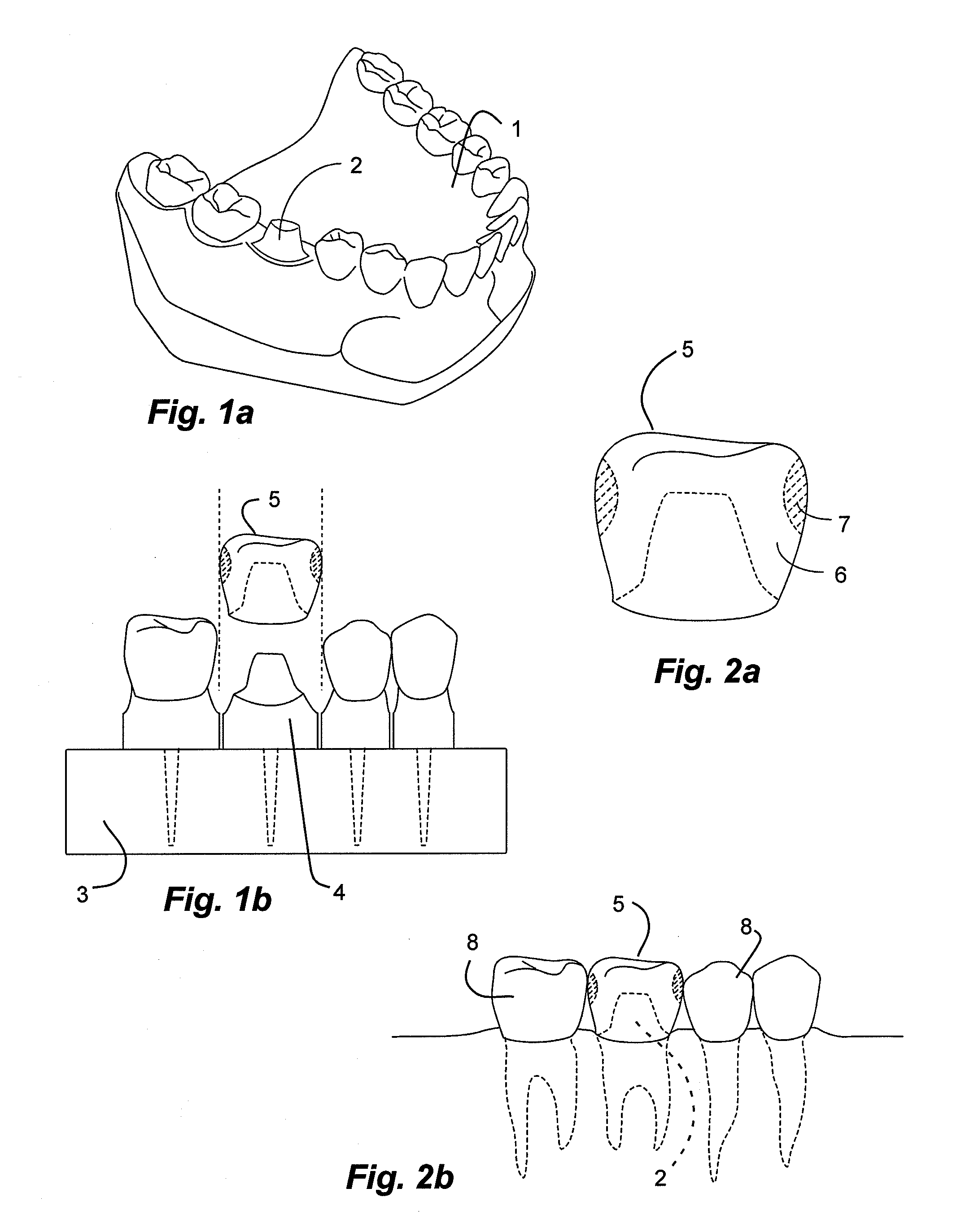
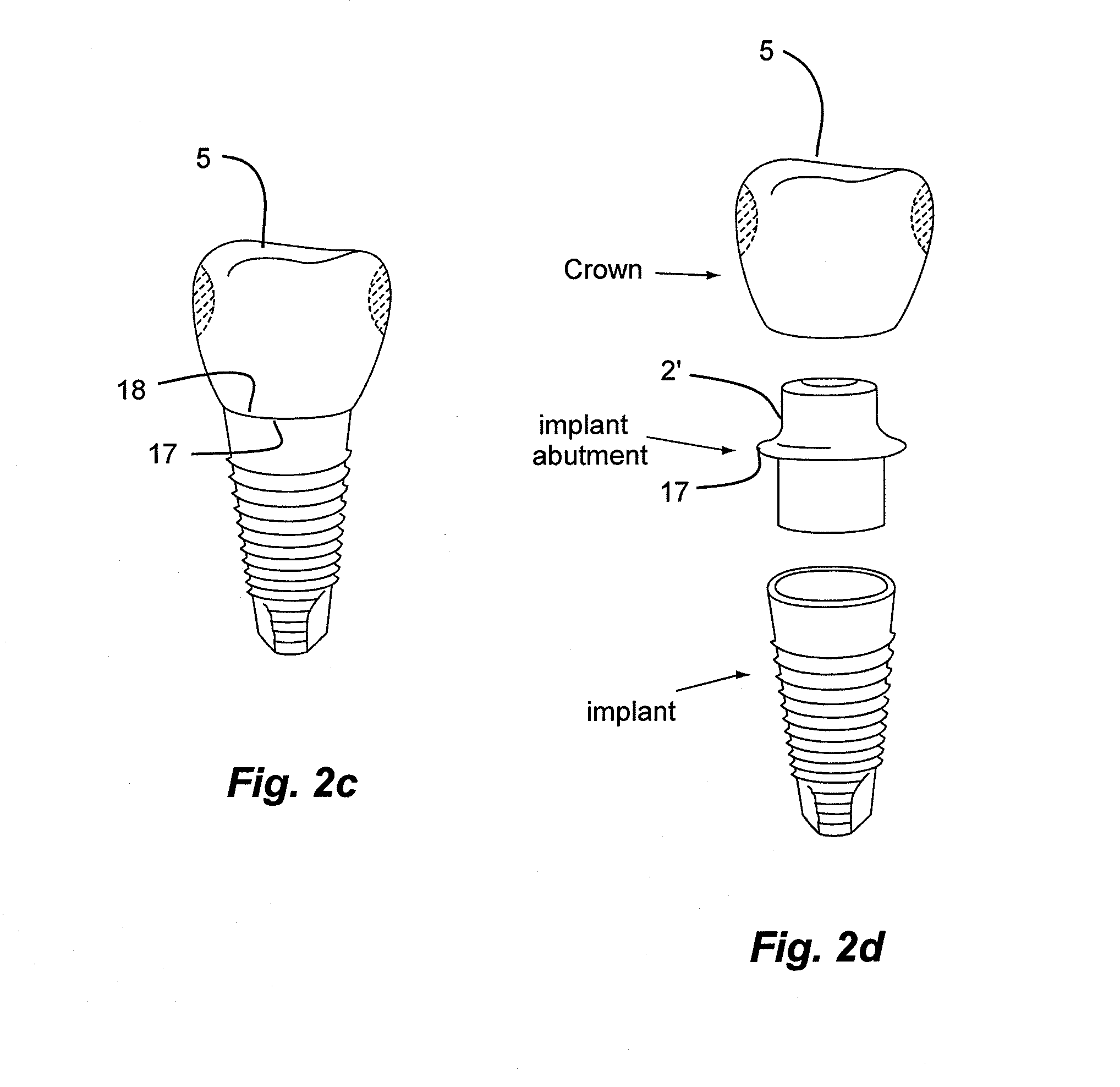
[0237](Margin line, Design of a crown with a closed contact) Margin line information of a cut tooth was received before starting to make a crown. As in FIG. 3, the crown margin line 18 was created to cause the crown margin line 18 and prepared tooth margin line 17 to correspond with each other. A full contour zirconia crown was first CAD (computer aided design) designed so that the mesial and distal area of the crown could abut with the adjacent human teeth, creating a closed contact as introduced in option 1-1 in FIG. 6.

[0238](Automated milling and manually creating the open space) Then this precursor crown, primarily made of ZrO2, was milled from a pre-sintered zirconia block using the CAD / CAM method. Afterwards, a small undercut 9 and / or 10 on each of the non-load bearing mesial and distal areas was created by grinding away the ceramic body portion with a hand tool, creating hollow open spaces 9 and / or 10 as shown in FIG. 6a...

example 2

Full Contour Zirconia, Automated Milling Machine Creates Open Space

[0244](Margin line, Design of a crown with an open contact) Margin line information of a cut tooth was received before starting to make a crown. The crown margin line 18 was created to cause the crown margin line 18 and prepared tooth margin line 17 to correspond with each other. A full contour zirconia crown was first CAD (computer aided design) designed so that the non-load bearing mesial and / or distal area could have an open space 9 and / or 10 away from the adjacent teeth 8, creating an open contact as introduced in option 2-1 in FIG. 6, or FIG. 20a or FIG. 21a.

[0245](Automated milling and mechanically creating the open space) Then this precursor crown 5′, primarily made of ZrO2, was milled from a pre-sintered zirconia block using the CAD / CAM method. At least one open space 9 and / or 10 was milled from the milling machine. The automated milling process can create the buccal contour 14 either before, or during, or a...

example 3

Full Contour Zirconia, Light Curing

[0251](Design of a restoration with or without an open space) A full contour zirconia crown was first CAD (computer aided design) designed on the computer monitor as in FIG. 6 so that the mesial and distal area could abut with the adjacent teeth 8 (option 1-1), creating a closed contact. Creating a closed contact generally means a restoration without an open space. An exception of this would be a case where an open space would exist outside the contact area. In other words, a precursor crown 5′ can have a closed contact and still have at least on open space as in FIG. 13d. Alternatively, as in FIG. 8, a full contour zirconia crown was first CAD (computer aided design) designed on the computer monitor so that the non-load bearing mesial and / or distal area can have an open space away from the adjacent teeth 8, creating an open contact 18. Alternatively, open contact of the inventive precursor crown 5′ can be created through option 2-1 of FIG. 6 or FI...


PUM

PropertyMeasurementUnit
temperatureaaaaaaaaaa
distanceaaaaaaaaaa

Abstract

A method of making a dental crown or bridge restoration comprises forming a precursor crown outside of a patient's mouth with a first restorative material, with a buccal contour on the buccal wall substantially the same as a buccal contour on a final crown restoration, and an open space on or around at least one of the mesial side wall or the distal side wall; and filling and securing a second material, different from the first restorative material, inside the open space or pocket of the precursor crown while outside the patient's mouth, and with the precursor crown having a strength substantially equivalent to the final crown restoration, and with the buccal contour being substantially the same as the buccal contour on the final crown, prior to filling and securing the second material.

Description

PRIORITY CLAIM[0001]Priority is claimed to copending U.S. Provisional Patent Application Ser. Nos. 61 / 892,345, filed Oct. 17, 2013, and 61 / 909,812, filed Nov. 27, 2013, which are hereby incorporated herein by reference in their entirety.BACKGROUND[0002]1. Field of the Invention[0003]The present invention relates generally to a method for making a dental restoration or prosthesis, such as a crown or a bridge. In particular, the present invention relates to a method for making a dental restoration with a second material filling a pocket in the dental restoration.[0004]2. Related Art[0005]Minimal intervention is a key phrase in today's dental practice. Minimal intervention dentistry (MID) focuses on the least invasive treatment options possible in order to minimize tissue loss and patient discomfort. Concentrating mainly on prevention and early intervention of caries, MID's first basic principle is the remineralization of early carious lesions, advocating a biological or therapeutic ap...

Claims


Application Information

Patent Timeline
Patent Type & Authority Applications(United States)
IPC IPC(8): A61C13/00A61C13/225A61C5/10A61C5/77
CPCA61C13/0003A61C13/225A61C5/10A61C9/002A61C13/0004A61C13/09A61C13/26A61C19/063A61C5/77Y10T29/49567
Inventor JUNG, DANIEL YONILJUNG, YUNOH
Owner B & D DENTAL
Why Eureka
Try Eureka