
Dual phase magnetic material component and method of forming

a technology of magnetic material and component, applied in the direction of magnetic bodies, heat treatment apparatus, furnaces, etc., can solve the problems of increasing coercivity and lowering the magnetic saturation

Active Publication Date: 2015-04-30
GENERAL ELECTRIC CO
View PDF7 Cites 41 Cited by
  • Summary
  • Abstract
  • Description
  • Claims
  • Application Information

AI Technical Summary

Benefits of technology

The invention discusses a new magnetic component with two different regions: one region is made of a magnetic material, and the other region is made of a non-magnetic material. These regions have a low concentration of carbon and a high concentration of nitrogen. The method for preparing this component involves using a nitrogen stop-off material to mechanically mask certain sections of the surface, and heat-treating the component in a nitrogen-rich atmosphere at a high temperature. This results in the formation of the intermixed first and second regions. This new type of magnetic component has unique properties that make it useful in a variety of applications.

Problems solved by technology

However, it is recognized that when electrical machines are used for traction applications in hybrid / electric vehicles, there is a clear tradeoff between power density, efficiency, and the machine's constant power speed range—and that this tradeoff presents numerous design challenges.
However, the presence of carbides in a magnetic microstructure is known to increase coercivity and to lower the magnetic saturation, as compared to traditional ferrous-based magnetic steels.

Method used


Image

  • Dual phase magnetic material component and method of forming
  • Dual phase magnetic material component and method of forming
  • Dual phase magnetic material component and method of forming

Examples


example

[0039]The example that follows is merely illustrative, and should not be construed to be any sort of limitation on the scope of the claimed invention. Unless specified otherwise, all ingredients may be commercially available from common chemical suppliers.

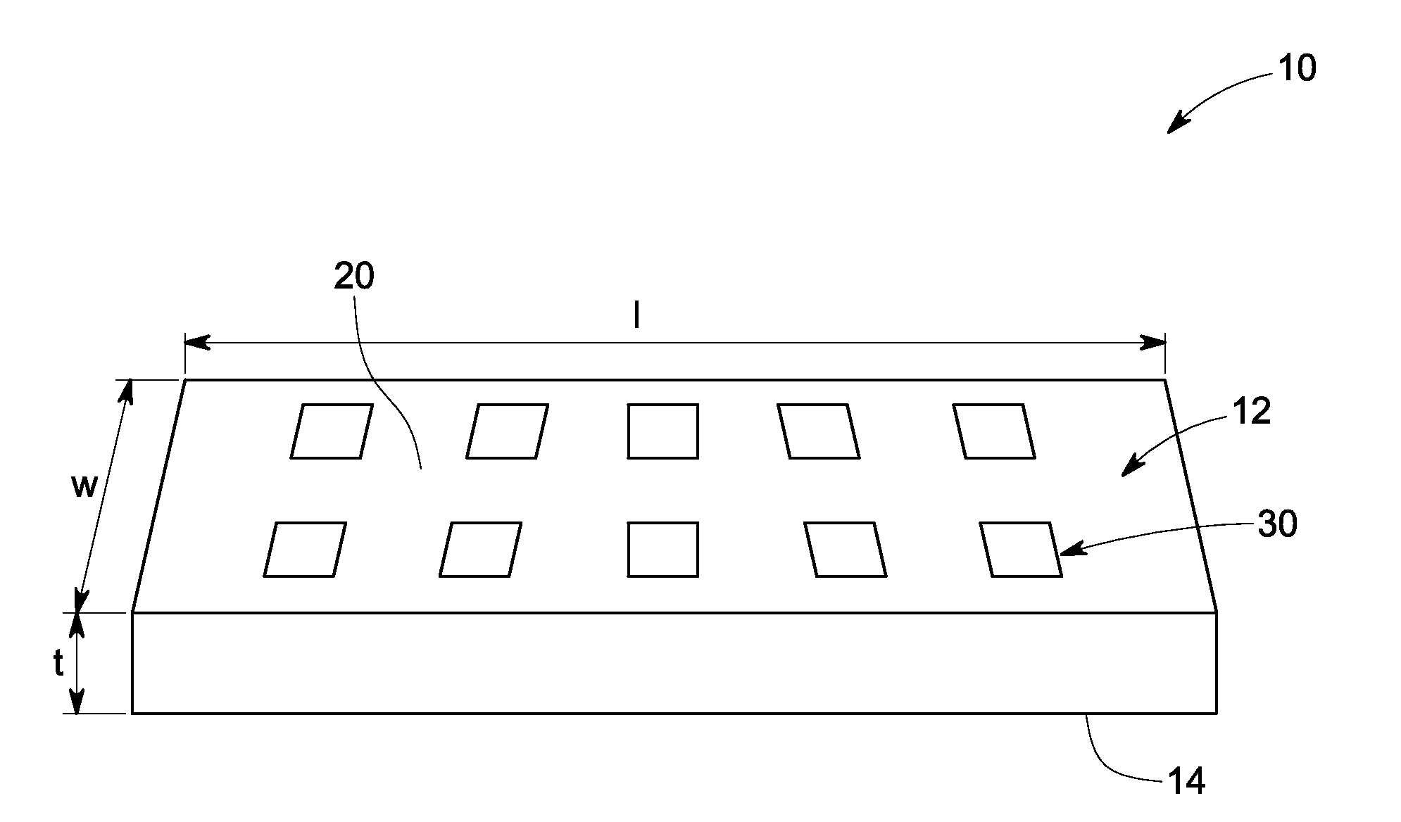
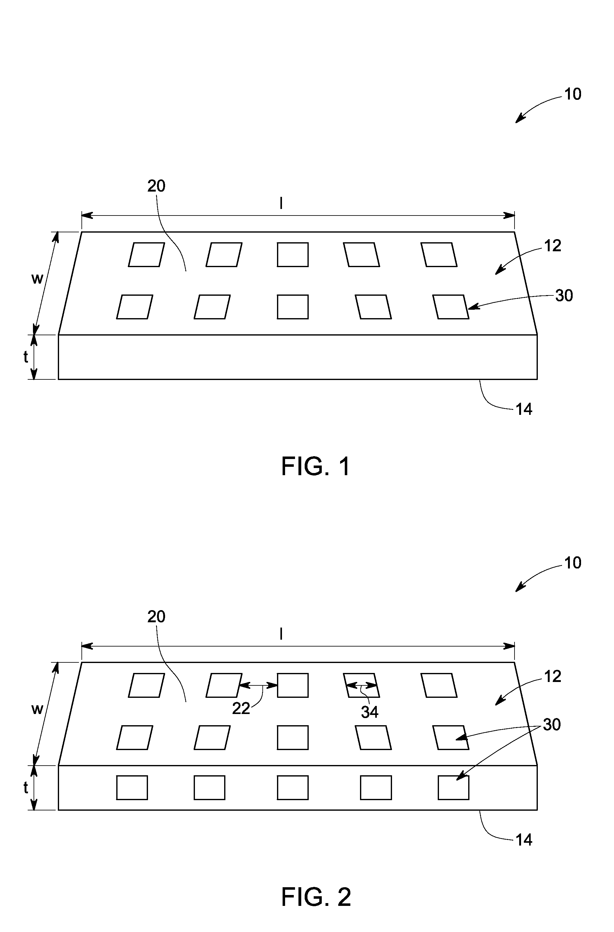
[0040]With reference, to FIG. 4, an example component 50 of Fe-20Cr-5Mn (in weight %) alloy was selected and was painted with a commercially available stop-off paint 52 over half the sample. The component was nitrided at 1150° C. in pure nitrogen at a pressure of 1 atm. FIG. 4 shows the cross-section along thickness t (as shown in FIG. 1) of the masked component 50 displaying the location of the stop off coating 52 used to mask the magnetic region 54 from nitriding. The region 56 was not masked and was exposed for nitriding. FIG. 5 generally shows the substantially ferritic microstructure of the magnetic region 54, and the changed, austenite microstructure in the region 56 that is exposed to nitriding. FIG. 5 further depicts the un...


PUM

PropertyMeasurementUnit
Temperatureaaaaaaaaaa
Fractionaaaaaaaaaa

Abstract

A magnetic component having intermixed first and second regions, and a method of preparing that magnetic component are disclosed. The first region includes a magnetic phase and the second region includes a non-magnetic phase. The method includes mechanically masking pre-selected sections of a surface portion of the component by using a nitrogen stop-off material and heat-treating the component in a nitrogen-rich atmosphere at a temperature greater than about 900° C. Both the first and second regions are substantially free of carbon, or contain only limited amounts of carbon; and the second region includes greater than about 0.1 weight % of nitrogen.

Description

STATEMENT REGARDING FEDERALLY SPONSORED RESEARCH & DEVELOPMENT[0001]This invention was made with Government support under contract number DE-EE0005573, awarded by the United States Department of Energy. The Government has certain rights in the invention.BACKGROUND[0002]The invention relates generally to a component having multiple magnetic and nonmagnetic regions, and a method of forming the same. More particularly, the invention relates to a component having multiple magnetic and nonmagnetic regions, and formation of the same by nitriding.[0003]The need for high power density and high efficiency electrical machines (i.e. electric motors and generators) has long been prevalent for a variety of applications, particularly for hybrid and / or electric vehicle traction applications. The current trend in hybrid / electric vehicle traction motor applications is to increase rotational speeds to increase the machine's power density, and hence reduce its mass and cost. However, it is recognized ...

Claims


Application Information

Patent Timeline
IPC IPC(8): H01F7/02H01F41/02H02K19/02C21D1/26C23C8/26H01F1/147C21D9/00
CPCH01F7/02H01F1/147H01F41/02C21D2221/00C21D1/26C23C8/26H02K19/02C21D9/00C23C8/04C21D1/06C22C38/38H02K15/12H02K19/103
Inventor DIAL, LAURA CERULLYDIDOMIZIO, RICHARDJOHNSON, FRANCIS
Owner GENERAL ELECTRIC CO
Learn More