Unlock instant, AI-driven research and patent intelligence for your innovation.

Near field communication system and method thereof

Active Publication Date: 2015-04-30
MAGNA ELECTRONICS SOLUTIONS
View PDF3 Cites 13 Cited by
  • Summary
  • Abstract
  • Description
  • Claims
  • Application Information

AI Technical Summary

Benefits of technology

The present invention is a system, apparatus, and method that uses an automatic coupling optimized NFC system. This means that no matter where the portable device is placed, the system can quickly and easily connect with it. The system uses a multiplexer to select which coils to use for a better connection, and an adaptation network to adjust for any disturbances in the connection. This ensures a stable connection no matter where the portable device is placed. Overall, this technology allows for quick and easy NFC connections in various locations.

Problems solved by technology

However, the location of the antenna integrated within the NFC device depends on different manufacturers and is not standardized.
This would cause a problem because the antenna within the initiator NFC device has to be placed right over the antenna of the NFC target device to ensure a proper EM field coupling and therefore a stable data transfer between the devices.
Therefore, how to ensure a stable data transmission under the random position of the NFC devices becomes a problem.
This solution is not ideal, because two NFC antennas with completely different size lead to a decreased coupling efficiency.
In addition, the electromagnetic power generated by the enabled coil may induce disturbance coupling effects with the nearby metals or other coils, and the disturbance coupling effects may decrease the coupling efficiency between the antenna 331 of the initiator NFC device 330 and the enabled coil of the target NFC device.

Method used


Image

  • Near field communication system and method thereof
  • Near field communication system and method thereof
  • Near field communication system and method thereof

Examples


first embodiment

[0044]Please refer to FIG. 4, which shows a communicating apparatus of the NFC system of the present invention. In this embodiment, one adaptation network 30 is electronically connected between the multiplexer 20 and the processor 40. The following will use this embodiment to describe how the NFC system 100 of the present invention works.

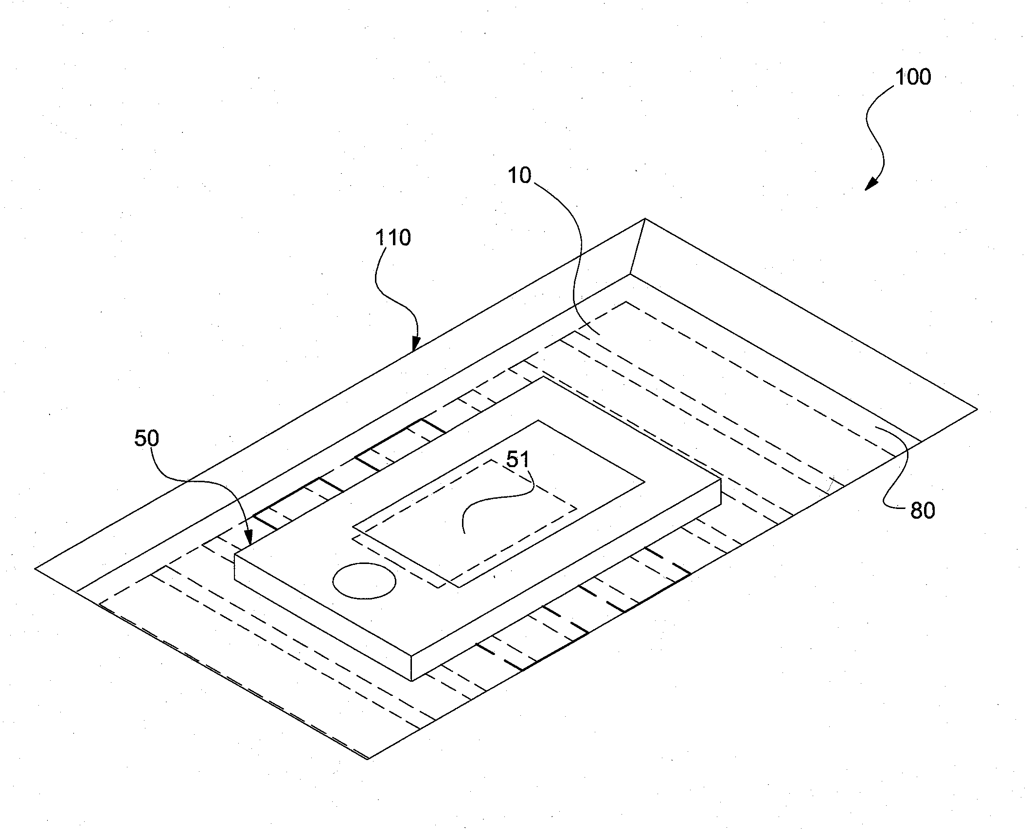
[0045]When the portable device 50 is placed on the communicating plane 80 of the communicating apparatus 110, an EM field 52 is generated between the antenna 51 of the portable device 50 and at least one of the coils 10. The strength / density distribution of the EM field 52 is related to the size of the antenna 51. Under this concept, at least one of the coils 10 is combined into an effective antenna 11 having the size equal or similar to that of the antenna 51 of the portable device 50 for reaching the best coupling effect. The term “the size of the effective antenna 11 is equal or similar to that of the antenna 51” used herein means that the physic...

second embodiment

[0050]Please refer FIG. 5, which shows a communicating apparatus of the NFC system of the present invention.

[0051]The setting and the numbers of the adaptation network 30 are optionally variable. In the exemplary embodiment of FIG. 4, one adaptation network 30 is electronically connected to the multiplexer 20, and the adaptation network 30 adapts the impedance or inductance of the effective antenna 11 which are enabled by the multiplexer 20. Namely, the adaptation network 30 is electronically connected between the multiplexer 20 and the processor 40. In the exemplary embodiment of FIG. 5, each of coils 10 is electronically connected with the adaptation network 30. Namely, the adaptation network 30 is electronically connected between the multiplexer 20 and each of the coils 10. The setting of the adaptation network 30 shown as FIG. 5 is more preferable because the adaptation network 30 has the better tuning possibilities for each coil 10.

[0052]Referring back to FIG. 3, the communicat...


PUM


Abstract

A near field communication (NFC) system includes a plurality of coils for coupling to an antenna of a portable device, wherein each two adjacent coils are partly overlapped with one another; a multiplexer selectively enabling at least one of the coils to build a communication with the antenna, wherein the coils enabled by the multiplexer are selected to have a best coupling effect with the antenna and are combined into an effective antenna; and at least one adaptation network for adapting an input / output of the effective antenna.

Description

BACKGROUND OF THE INVENTION[0001]1. Field of the Invention[0002]The present invention relates to a near field communication system. In particular, the present invention relates to a near field communication system ensuring that the communication is stable regardless of the location of the antenna of a portable device.[0003]2. Description of the Related Art[0004]Near field communication (NFC) is a wireless and contactless communication technology, and it is widely used in many apparatus and devices; such as smart card, smart phone or tablet computer. The NFC technology uses magnetic induction to transfer data from one antenna to another antenna over a very short distance, usually no more than a few inches. Namely, an initiator device uses an antenna to generate an electro-magnetic (EM) field, and a target device which is positioned in the “near-field” area of the generated EM field would use the antenna of the target device (such as a coil) to couple with the antenna of the initiator...

Claims


Application Information

Patent Timeline
IPC IPC(8): H04W4/00H04B5/00H04W4/80
CPCH04B5/0081H04W4/008H04W4/80H04B5/263H04B5/72H04B5/00H04B5/26H04B5/24H04B5/79
Inventor SCHAEFER, MARCGRAF, STEFAN
Owner MAGNA ELECTRONICS SOLUTIONS