
Speed change control system for vehicles

a control system and vehicle technology, applied in mechanical equipment, machines/engines, instruments, etc., can solve problems such as torque reduction, “retraction” feeling, and shocks, and achieve the effects of reducing shift shocks, reducing shift shocks and damage of engagement devices

Active Publication Date: 2015-04-30
TOYOTA JIDOSHA KK
View PDF3 Cites 10 Cited by
  • Summary
  • Abstract
  • Description
  • Claims
  • Application Information

AI Technical Summary

Benefits of technology

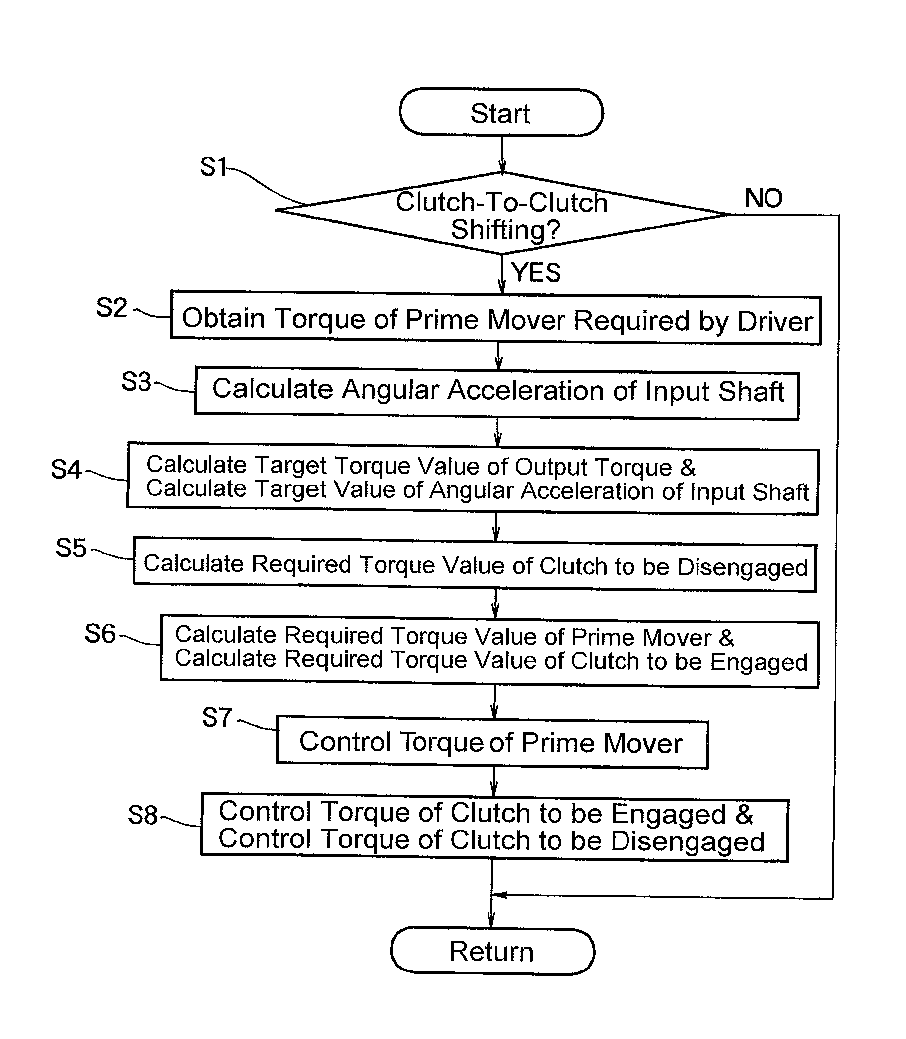
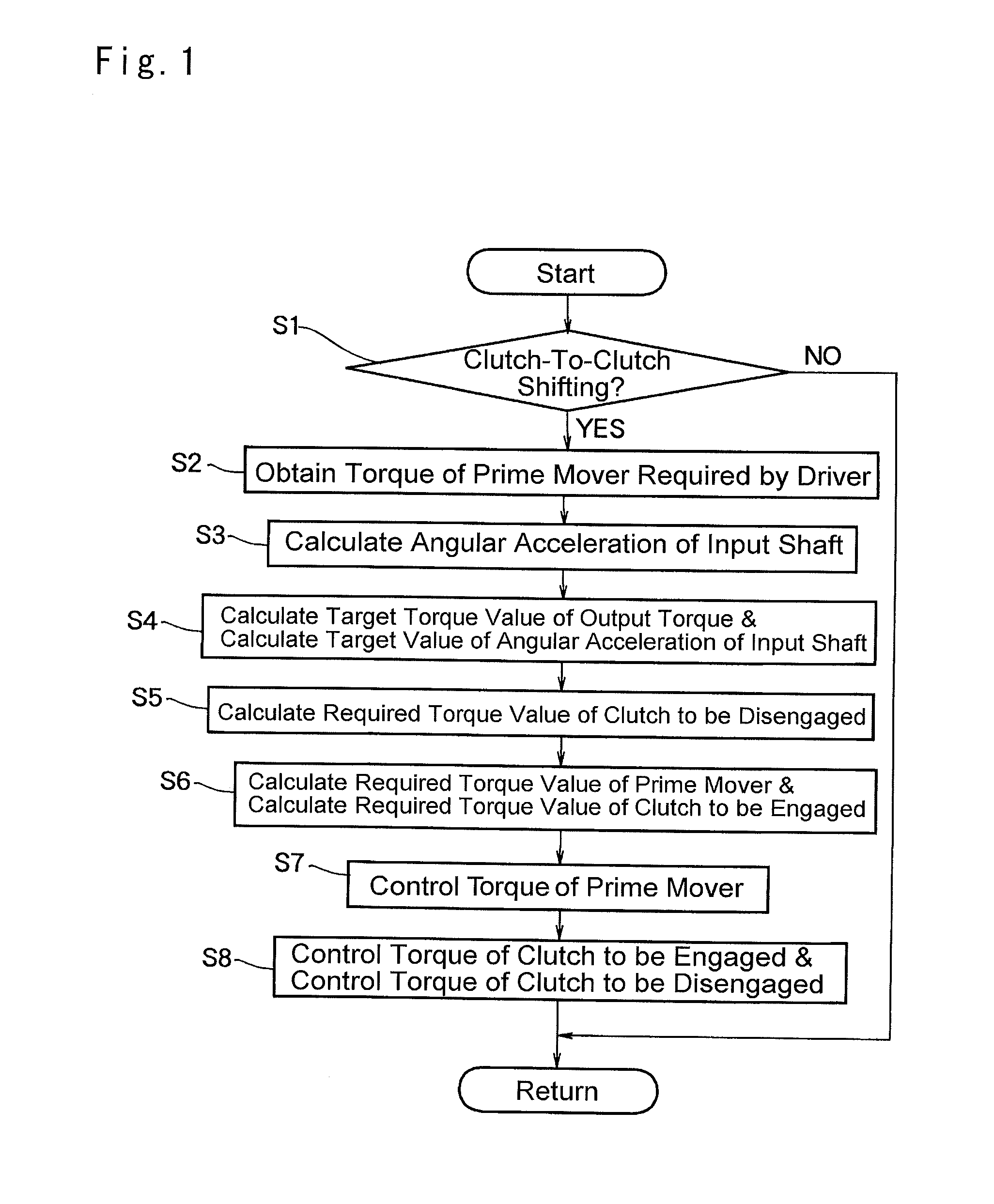
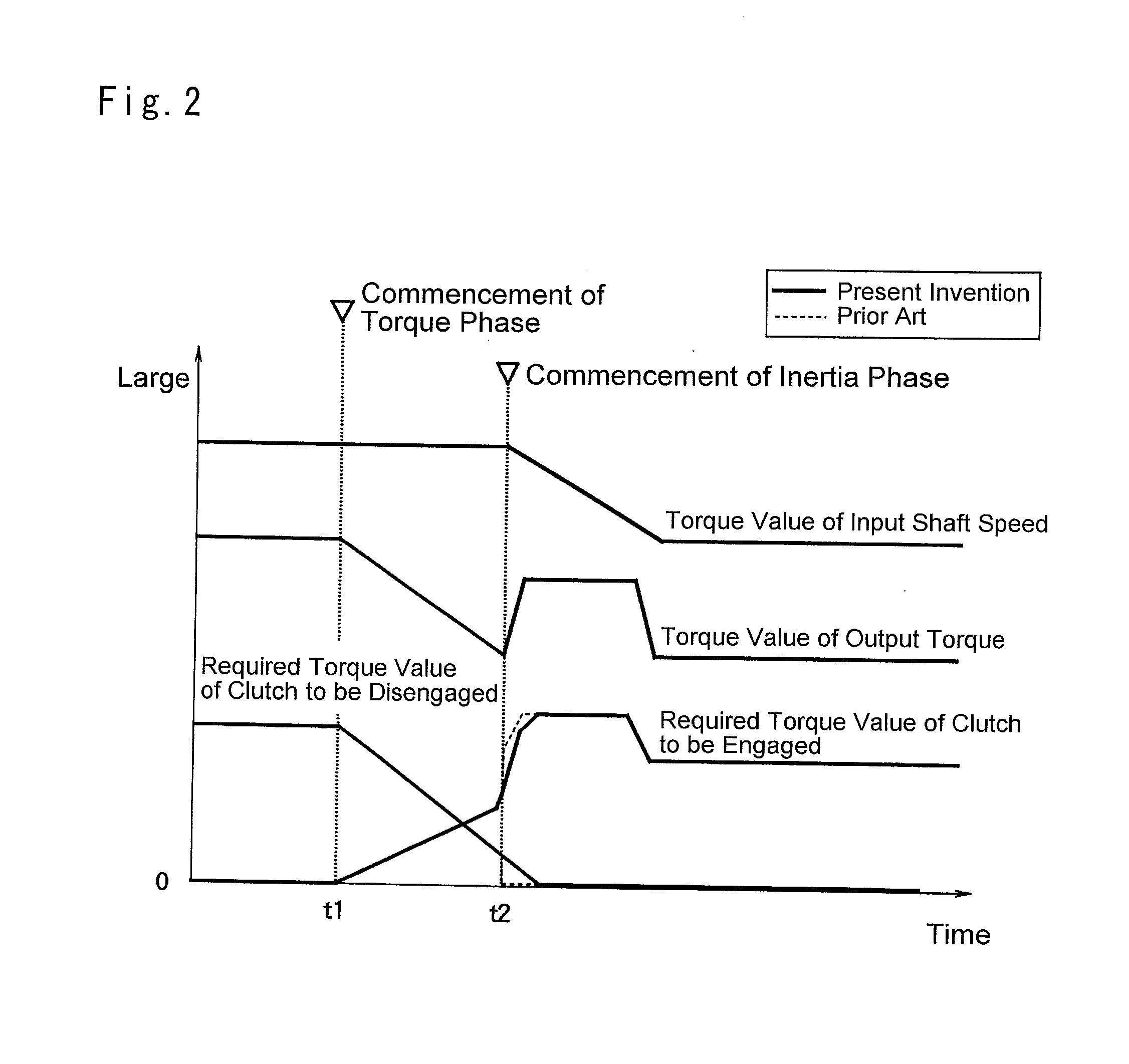
The present invention relates to a speed change control system for vehicles that uses a transmission with multiple engagement devices. The system is designed to shift gear stages by gradually increasing or decreasing the torque capacity of engagement devices. The control system uses a torque calculation to determine the target torque capacity of the engagement devices during the torque phase and inertia phase of shifting. The target torque capacity of the engagement device to be disengaged is also changed continuously to prevent sudden changes in drive torque and reduce shift shocks and damage to the engagement devices. The control system also includes a means to control the output torque of the prime mover to further reduce shift shocks and damage.

Problems solved by technology

However, if torque transmitting capacities of both engagement devices to be engaged and disengaged are insufficient during the clutch-to-clutch shifting, so-called a “retraction” feeling may be caused by a torque drop.
By contrast, if torque transmitting capacities of both engagement devices to be engaged and disengaged are excessive, shocks may be caused by a torque reduction resulting from a transmission tie-up.
By contrast, if the torque transmitting capacity of the clutch to be engaged is excessive, the “retraction” feeling may be caused by a torque drop resulting from the transmission tie-up.
Thus, the torque transmitting capacity of the clutch or the hydraulic pressure applied thereto has to be controlled irregularly thereby causing shift shocks.
Therefore, the teachings of Japanese Patent Laid-Open No. 2001-227637 may not be applied to control entire course of the clutch-to-clutch shifting.

Method used


Image

  • Speed change control system for vehicles
  • Speed change control system for vehicles
  • Speed change control system for vehicles

Examples


Embodiment Construction

[0015]The present invention is directed to a control system for a clutch-to clutch shifting of an automatic transmission of a vehicle. FIG. 3 is a block diagram schematically illustrating a preferred example of the vehicle to which the control system applied. As shown in FIG. 3, an automatic transmission 3 is connected to a prime mover 1 through an output shaft 2. According to the preferred example, the prime mover 1 includes an internal combustion engine such as a gasoline engine and a diesel engine, a motor, and a hybrid power source having the engine and the motor. For example, given that the gasoline engine is employed as the prime mover 1, the prime mover 1 is provided with an electronic throttle valve to electrically control an output torque thereof. In this case, specifically, the output torque is generated according to an air intake by electrically controlling an opening degree of the electronic throttle valve, and the output torque is changed temporarily by delaying or adva...


PUM


Abstract

A speed change control system for reducing shift shocks of clutch-to-clutch shifting is provided. The control system is applied to a vehicle in which a transmission having a plurality of engagement devices is connected to an output side of a prime mover, and in which a gear stage of the transmission is shifted among a plurality of stages by changing engagement states of the engagement devices. The speed change control system is configured to carry out a clutch-to-clutch shifting of the gear stage from a predetermined gear stage to another gear stage by gradually reducing a torque capacity of the predetermined engagement device to be disengaged while gradually increasing a torque capacity of another engagement device to be engaged. The speed change control system is comprised of a torque calculation means that calculates a target torque capacity of the engagement device to be engaged during a torque phase and an inertia phase under the clutch-to-clutch shifting, based on a target input angular acceleration of the transmission, a target output angular acceleration of the transmission, a target torque capacity of the engagement device to be disengaged, and a target output torque, and configured to change the target torque capacity of the engagement device to be disengaged continuously from the torque phase to the inertia phase under the clutch-to-clutch shifting.

Description

TECHNICAL FIELD[0001]The present invention relates generally to a system for controlling a speed change operation of an automobile, and more particularly, to a system configured to shift a gear stage while engaging or disengaging an engagement device such as a clutch and a brake.BACKGROUND ART[0002]A speed ratio of an automobile is governed by a mechanism for transmitting torque from a prime mover such as an engine to drive wheels. In general, a gear stage of a vehicle transmission including a forward stage and a reverse stage is selected by selecting a gear pair for transmitting the torque from a plurality of gear pairs by a clutch. Given that the transmission is formed by combining a plurality of planetary gear units, a torque transmission route is changed depending on engagement states of a clutch and a brake. Alternatively, the gear stage of the transmission may also be shifted by changing engagement states of the clutch and the brake thereby changing a reaction element or an ou...

Claims


Application Information

Patent Timeline
Patent Type & Authority Applications(United States)
IPC IPC(8): B60W30/19B60W10/11F16H61/06B60W10/04
CPCB60W30/19B60W10/04F16H2306/42F16H61/061F16H2302/00B60W10/11B60W2710/1016F02D29/00F16H61/06F16H61/684F16H2059/405F16H2059/425
Inventor MASUNAGA, SEIJIHASEFAWA, YOSHIOKUWAHARA, SEIJIKOBAYASHI, NOBUFUSA
Owner TOYOTA JIDOSHA KK
Learn More