
Direct Electrical Steam Generation for Downhole Heavy Oil Stimulation

a technology of electrical steam and stimulation, which is applied in the direction of insulation, chemistry apparatus and processes, and wellbore/well accessories, etc., can solve the problems of poor or no stimulation, high energy content of steam lost during delivery, and complicated system subject to installation difficulty, so as to reduce oil viscosity and increase the quality of steam injected downhol

Active Publication Date: 2015-05-07
DONALDSON ENG INC
View PDF2 Cites 3 Cited by
  • Summary
  • Abstract
  • Description
  • Claims
  • Application Information

AI Technical Summary

Benefits of technology

This patent describes three methods for producing hydrogen and oxygen in a downhole environment. The first method involves using electrolysis of water to produce hydrogen and carbon dioxide through oxidation of in-situ oil. This helps to decrease oil viscosity. The second method involves a combustion process that increases the quality of steam injected downhole. The third method involves using a downhole sucker rod pump and an electric steam generator, which eliminates the need for a workover rig when huff-and-puff is used for sequential stimulation and production. Overall, these methods provide ways to generate energy and improve downhole production efficiency.

Problems solved by technology

While many heavy oil formations can be stimulated to production by steam delivered from conventional surface boilers to the formation via injection tubing, there are other formations which are either too deep, or of such poor injectivity that much of the energy content of the steam is lost during delivery, and the result is poor or no stimulation.
These efforts focused on the use of low cost fuel as an energy source, but the delivery of these feeds to a downhole steam generator, and control of these feeds from surface metering and control methods, resulted in a complicated system subject to difficulty of installation, difficulty with monitoring and control and associated high costs of materials and labor.
Air injection can initiate cyclic combustion which can be controlled by subsequent daily steam injection, thus minimizing channeling, which is a known problem with in-situ combustion projects.

Method used


Image

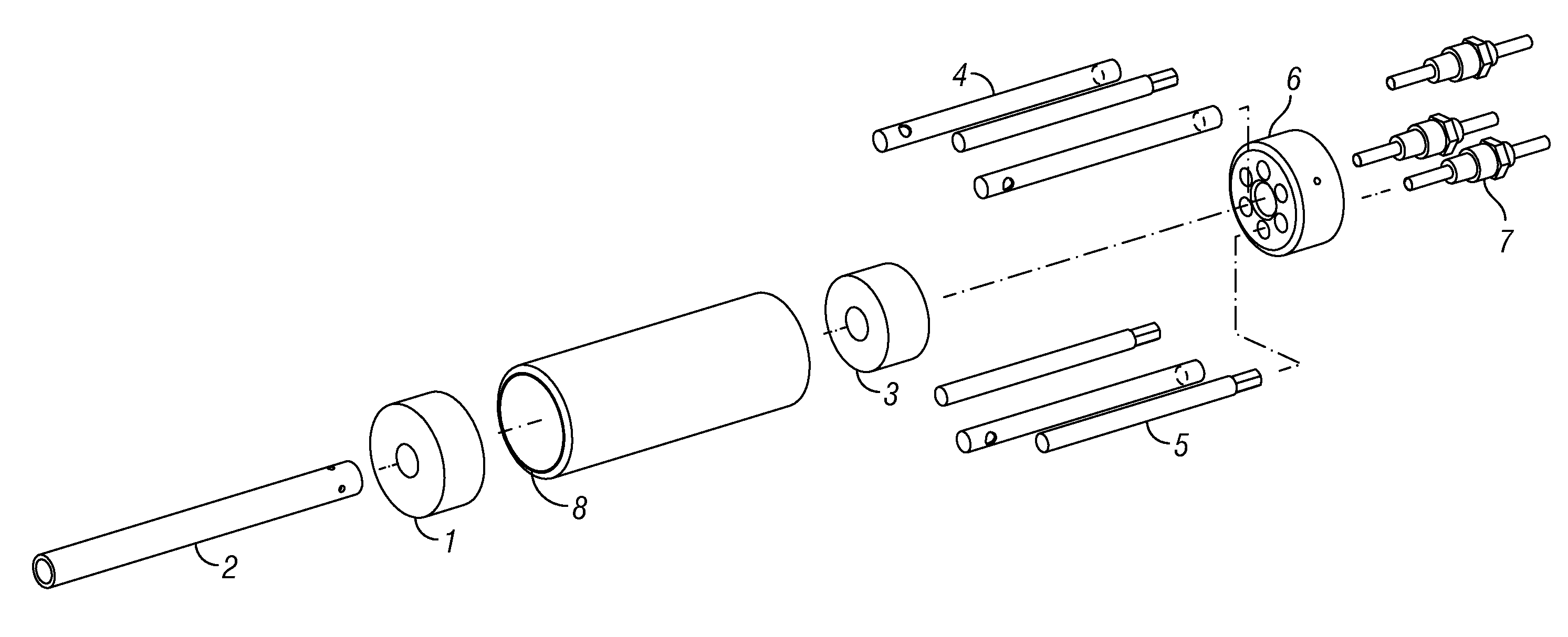
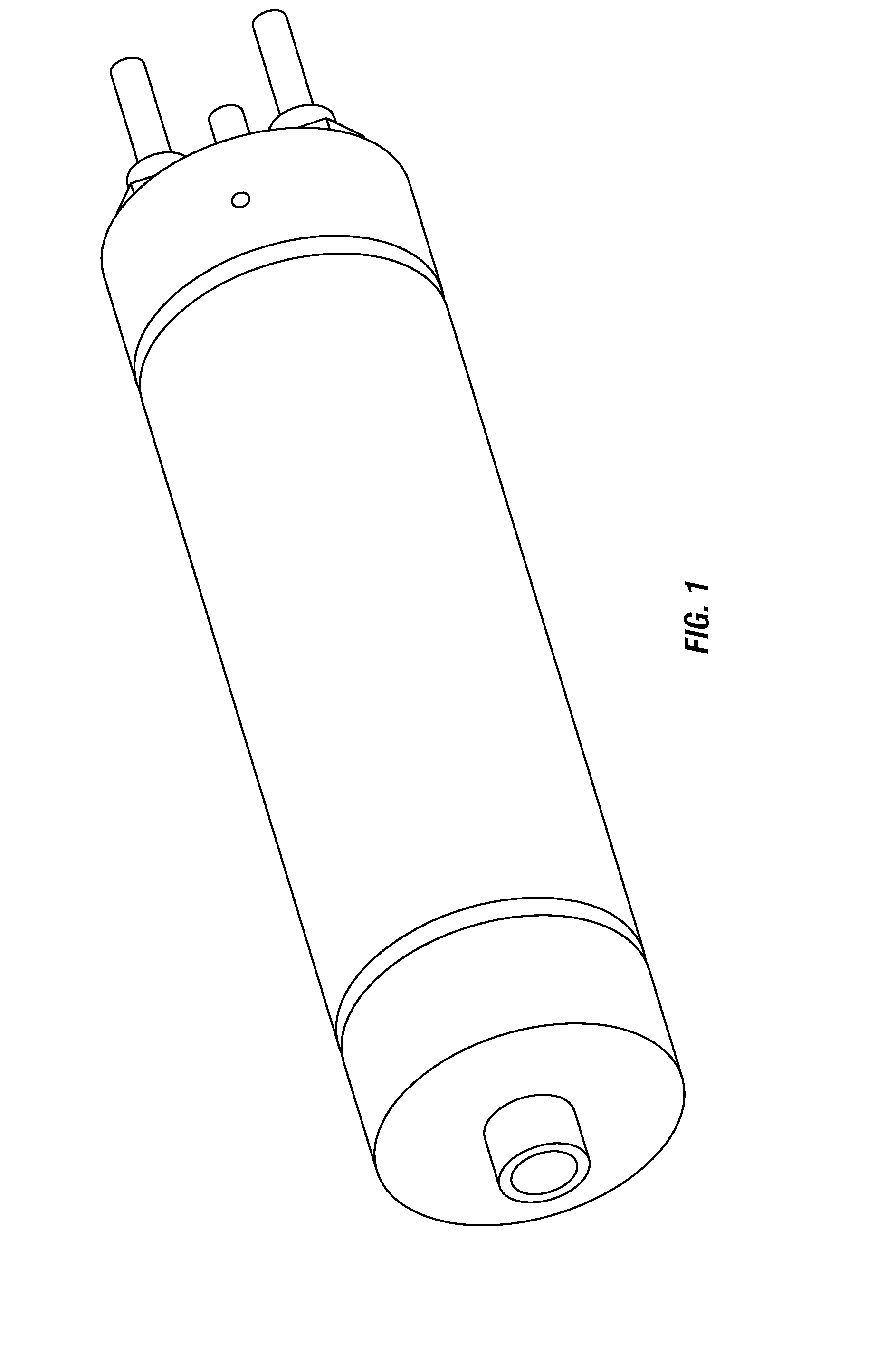
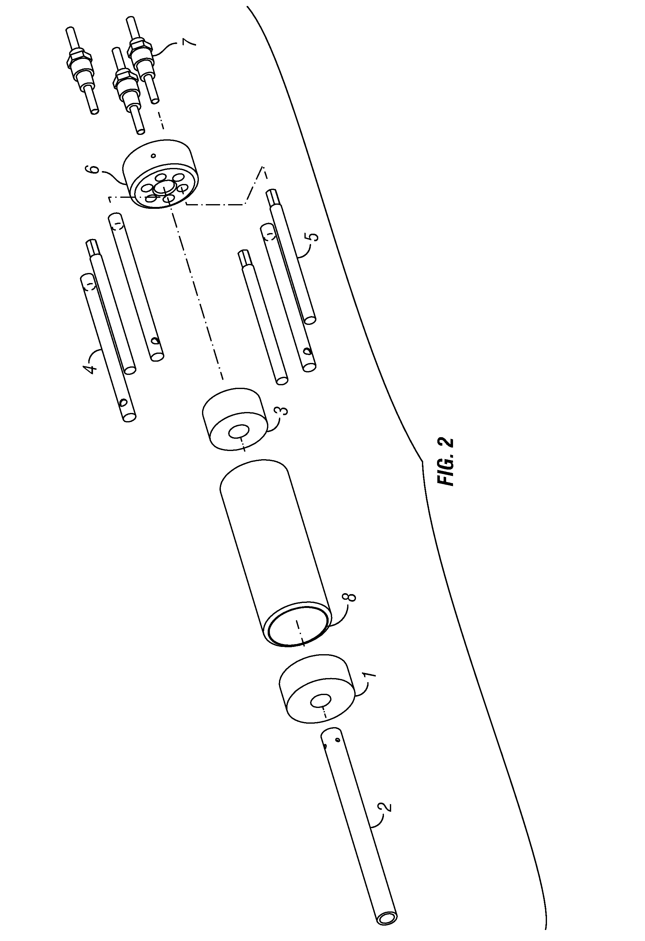
  • Direct Electrical Steam Generation for Downhole Heavy Oil Stimulation
  • Direct Electrical Steam Generation for Downhole Heavy Oil Stimulation
  • Direct Electrical Steam Generation for Downhole Heavy Oil Stimulation

Examples


Embodiment Construction

[0021]Steam is the traditional method of conveying heat into an oil formation, and the objective of raising formation temperature is a reduction in viscosity of heavy oil whose production is inhibited because of its high viscosity. Steam is a preferred heat transfer medium for various reasons, including: low cost, non-toxic, available, and its ability to carry substantial energy via latent heat of vaporization at relatively low temperatures. If the oil bearing formation is shallow, i.e., less that 2500′, and the “injectivity” of the formation is high, then output of traditional surface steam generators can be conveyed downhole without excessive heat loss. However, for deep heavy oil formations, or for formations with low injectivity, then delivery string heat losses dominate the process with a resultant low efficiency.

[0022]The basis for the method to be described relates to water electrical conductivity containing some level of ionic contaminants (electrolyte solution), which will ...


PUM

PropertyMeasurementUnit
mass fractionaaaaaaaaaa
pressureaaaaaaaaaa

Abstract

A method of downhole steam generation comprising determining a desired level of electrical conductivity for water to be converted to steam in a downhole location, acquiring a main feedwater supply, wherein water of the main feedwater supply has an electrical conductivity lower or higher than the desired level, mixing water of the main feedwater supply with water from one or more sidestreams to generate a resultant stream with an electrical conductivity of about the desired level, pumping the resultant stream to the downhole location, and passing an electrical current through the resultant stream in the downhole location to generate steam.

Description

CROSS-REFERENCE TO RELATED APPLICATIONS[0001]This application claims priority to and the benefit of the filing of U.S. Provisional Patent Application Ser. No. 61 / 899,504, entitled “Direct Electrical Steam Generation for Downhole Heavy Oil Stimulation”, filed on Nov. 4, 2013, and the specification and claims thereof are incorporated herein by reference.STATEMENT REGARDING FEDERALLY SPONSORED RESEARCH OR DEVELOPMENT[0002]Not Applicable.INCORPORATION BY REFERENCE OF MATERIAL SUBMITTED ON A COMPACT DISC[0003]Not Applicable.COPYRIGHTED MATERIAL[0004]Not Applicable.BACKGROUND OF THE INVENTION[0005]1. Field of the Invention (Technical Field)[0006]The present invention relates to the generation of steam by direct electric heating of water containing dissolved or ionic solids. The immediate application is for generation of steam downhole in an oil bearing formation for improved production of heavy oil.[0007]2. Description of Related Art[0008]While many heavy oil formations can be stimulated ...

Claims


Application Information

Patent Timeline
Patent Type & Authority Applications(United States)
IPC IPC(8): E21B43/24E21B36/00C01B32/50
CPCE21B36/006E21B43/2401E21B43/24Y02E60/36Y02E60/32
Inventor DONALDSON, A. BURL
Owner DONALDSON ENG INC
Learn More