Level shift circuit and dc-dc converter for using the same

a level shift circuit and converter technology, applied in logic circuit coupling/interface arrangement, pulse technique, instruments, etc., can solve the problems of large power consumption and leakage paths, poor anti-interference ability of pulse type level shift circuits, and inconvenient light-load operation, so as to reduce power consumption and avoid logic error level of output signals.

Active Publication Date: 2015-05-14
GREEN SOLUTION TECH CO LTD
View PDF7 Cites 24 Cited by
  • Summary
  • Abstract
  • Description
  • Claims
  • Application Information

AI Technical Summary

Benefits of technology

[0014]In view of the problems of the level shift circuit of the prior art, the level shift circuit of the present invention can avoid the level shift circuit consuming additional curre...

Problems solved by technology

However, the conventional current type level shift circuit has a large power consumption and leakage paths, and so is not suitable for light-load.
Thus, the anti-interference ability of the pulse type level shift circuit is very poor.
However, such circuit design has the higher power consumption.
In this mode, the larger current continuously flowing through the current type level shift circuit is not conducive to power-saving.
However, large power consumption problem still exists.
Advantages of the pulse type level shift circuit are speeding up the translating speed of the level shift due to the large current flowing through the pulse type level shift circuit, and lowering power consumption due to no current consumption after level shift has completed.
However, the pulse ...

Method used


Image

  • Level shift circuit and dc-dc converter for using the same
  • Level shift circuit and dc-dc converter for using the same
  • Level shift circuit and dc-dc converter for using the same

Examples


Embodiment Construction

[0039]In the following detailed description, for purposes of explanation, numerous specific details are set forth in order to provide a thorough understanding of the disclosed embodiments, it will be apparent, however, that one or more embodiments may be practiced without these specific details. In other instances, well-known structures and devices are schematically shown in order to simplify the drawings.

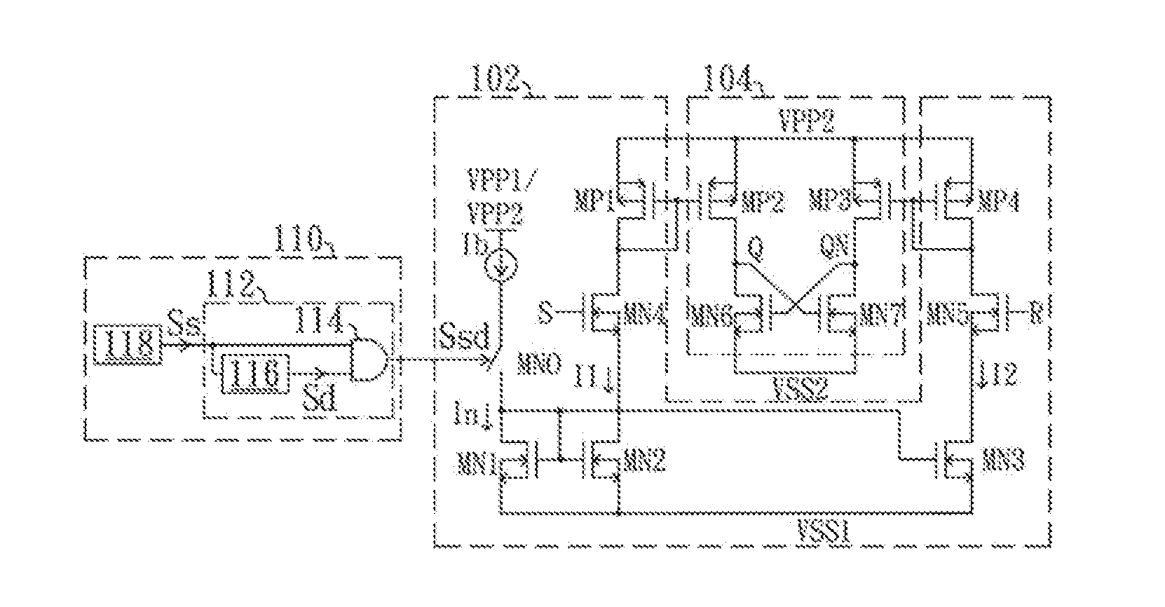
[0040]FIG. 8 is a schematic diagram of a level shift circuit according to a first preferred embodiment of the present invention. The level shift circuit comprises a signal input circuit 102, a signal output circuit 104 and a state detecting circuit 110. The signal input circuit 102 is coupled between a first level VSS1 and a second level VPP2, configured to receive a first input signal S and a second input signal R. Also referring to FIG. 9, FIG. 9 shows waveform diagrams of the level shift circuit shown in FIG. 8. Levels of the first input signal S and the second input signal R ar...


PUM


Abstract

A level shift circuit and a DC-DC buck converter controller for using the same are disclosed. The level shift circuit is capable of detecting a state of a converting circuit, and avoids a current leakage when determining that the converting circuit is operating under a light-load. Therefore, the level shift circuit and the DC-DC converting controller provided by the present invention can reduce power consumption under the light-load and have power-saving advantage.

Description

RELATED APPLICATIONS[0001]This application claims priority to Chinese Application Serial Number 201310561010.8, filed Nov. 12, 2013, which is herein incorporated by reference.BACKGROUND[0002]1. Field of Invention[0003]The invention relates to a level shift circuit and a DC-DC buck converter controller for using the same, and more particularly relates to a level shift circuit with a power-saving function and a DC-DC buck converter controller for using the same.[0004]2. Description of Related Art[0005]In the conventional DC-DC buck converting circuit, a level shift circuit is required to adjust the signal level for correctly turn on and off the high-side transistor of an N-type MOSFET. However, the conventional current type level shift circuit has a large power consumption and leakage paths, and so is not suitable for light-load. On the other hand, the conventional pulse type level shift circuit has no problems of leakage paths and large power consumption, but the pulse type level shi...

Claims


Application Information

Patent Timeline
IPC IPC(8): H03K19/00H02M3/158H03K19/0185
CPCH03K19/0013H02M3/158H03K19/018507H02M3/1588Y02B70/10
Inventor LEE, LI-MINSHAO, CHAOGAN, QUANCAI, YUAN
Owner GREEN SOLUTION TECH CO LTD
Why Eureka
Try Eureka