
MEMS Optical Sensor

a technology of optical sensors and optical sensors, applied in the direction of measuring force variation by measuring optical properties, instruments, material analysis, etc., can solve the problems of inability to achieve low coupling losses, undesirable higher order modes, and difficult to realize, so as to and improve the sensitivity of the sensor system

Active Publication Date: 2015-05-14
DANMARKS TEKNISKE UNIV
View PDF1 Cites 9 Cited by
  • Summary
  • Abstract
  • Description
  • Claims
  • Application Information

AI Technical Summary

Benefits of technology

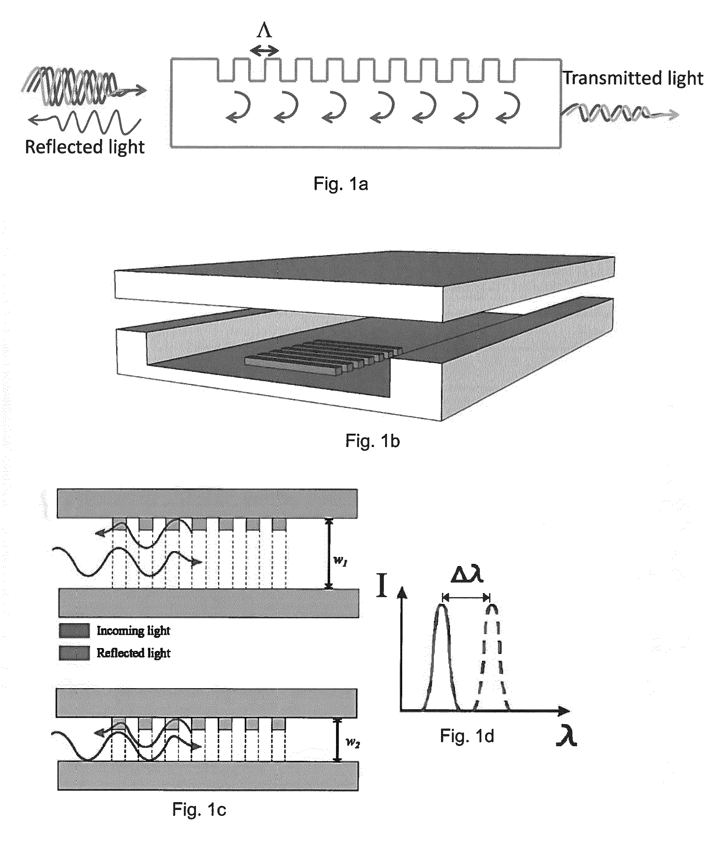
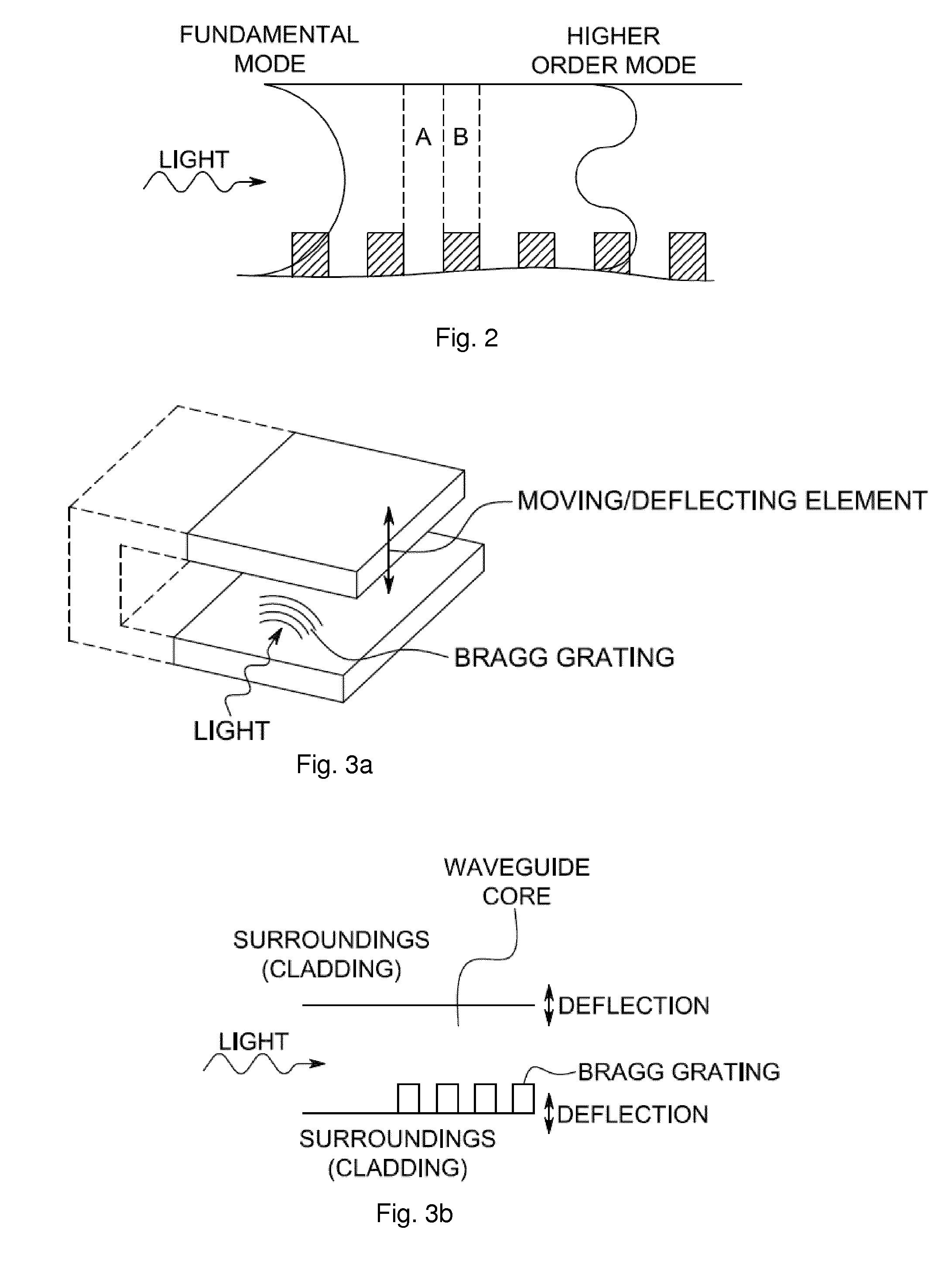
The present inventors have discovered that higher order modes are much more desirable for sensing applications than lower order modes. In multimode waveguides, the individual mode shapes differ in their spatial distribution, resulting in different modes having different sensitivity to changes in waveguide dimensions. By using higher order modes, the sensitivity of the sensor can be greatly improved. This invention allows for the creation of optical sensors that have simple geometry and are more sensitive to force, which makes them better suited for applications such as force sensing. The method can also be used to improve the sensitivity of existing optical sensors that guide higher order modes.

Problems solved by technology

However, even with MEMS technology these waveguide designs turned out to be difficult to realise in practise and consistently low coupling losses could not be obtained.
In the scientific community higher order modes are considered undesirable as they are more difficult to control.

Method used


Image

  • MEMS Optical Sensor
  • MEMS Optical Sensor
  • MEMS Optical Sensor

Examples


Embodiment Construction

[0042]The sensing method of all-optical sensors can in general be divided into amplitude modulated (AM) and frequency modulated (FM) sensing. Frequency modulation refers to the fact that changes in wavelength of the reflected light are used for determining the physical quantity measured, rather than the amplitude of the reflected light as in amplitude modulation. While AM based sensors can achieve extremely high sensitivities due to the on / off characteristics of the signal, the signal is inherently very vulnerable to transmission loss and noise and they are not easily integrated into larger sensor arrays since each sensor requires its own transmission line. On the other hand, FM based sensors do not have nearly the same sensitivity as AM based sensors, however, they are much more robust with respect to noise and are easily integrated into large distributed sensor systems as multiple sensors can share one transmission line.

[0043]In most optical waveguides the light is confined inside...


PUM


Abstract

The present invention relates to an all-optical sensor utilizing effective index modulation of a waveguide and detection of a wavelength shift of reflected light and a force sensing system accommodating said optical sensor. One embodiment of the invention relates to a sensor system comprising at least one multimode light source, one or more optical sensors comprising a multimode sensor optical waveguide accommodating a distributed Bragg reflector, at least one transmitting optical waveguide for guiding light from said at least one light source to said one or more multimode sensor optical waveguides, a detector for measuring light reflected from said Bragg reflector in said one or more multimode sensor optical waveguides, and a data processor adapted for analyzing variations in the Bragg wavelength of at least one higher order mode of the reflected light.

Description

[0001]The present invention relates to an all-optical sensor utilizing effective index modulation of a waveguide and detection of a wavelength shift of reflected light and a force sensing system accommodating said optical sensor.BACKGROUND OF INVENTION[0002]A sensor is a device that detects a specific physical quantity belonging to the sensor environment, through the means of one or more detection mechanisms which converts the physical quantity to a sensor specific output signal. Well known examples of often used sensors include thermometers, speedometers, microphones, voltmeters, radars and seismometers. A subset of the general sensor concept is the mechanical sensors which detects a property of classical mechanics, e.g. acceleration, pressure and strain, and should be distinguished from sensors used for e.g. biological, medical and chemical sensing. The vast majority of modern mechanical sensors are made using microelectromechanical system (MEMS) technology, as MEMS allows for sma...

Claims


Application Information

Patent Timeline
IPC IPC(8): G01L1/24G02B6/10G01N21/55
CPCG01L1/246G01N21/55G01N2201/0633G01N2201/084G01N2201/061G02B6/10G01L11/02
Inventor RECK, KASPEROSTERGAARD, CHRISTIANHANSEN, OLETHOMSEN, ERIK VILAIN
Owner DANMARKS TEKNISKE UNIV
Learn More