

Supercontinuum light source, a system and a method of measuring
- Summary
- Abstract
- Description
- Claims
- Application Information
AI Technical Summary
Benefits of technology
Problems solved by technology
Method used
Image

Examples
Embodiment Construction
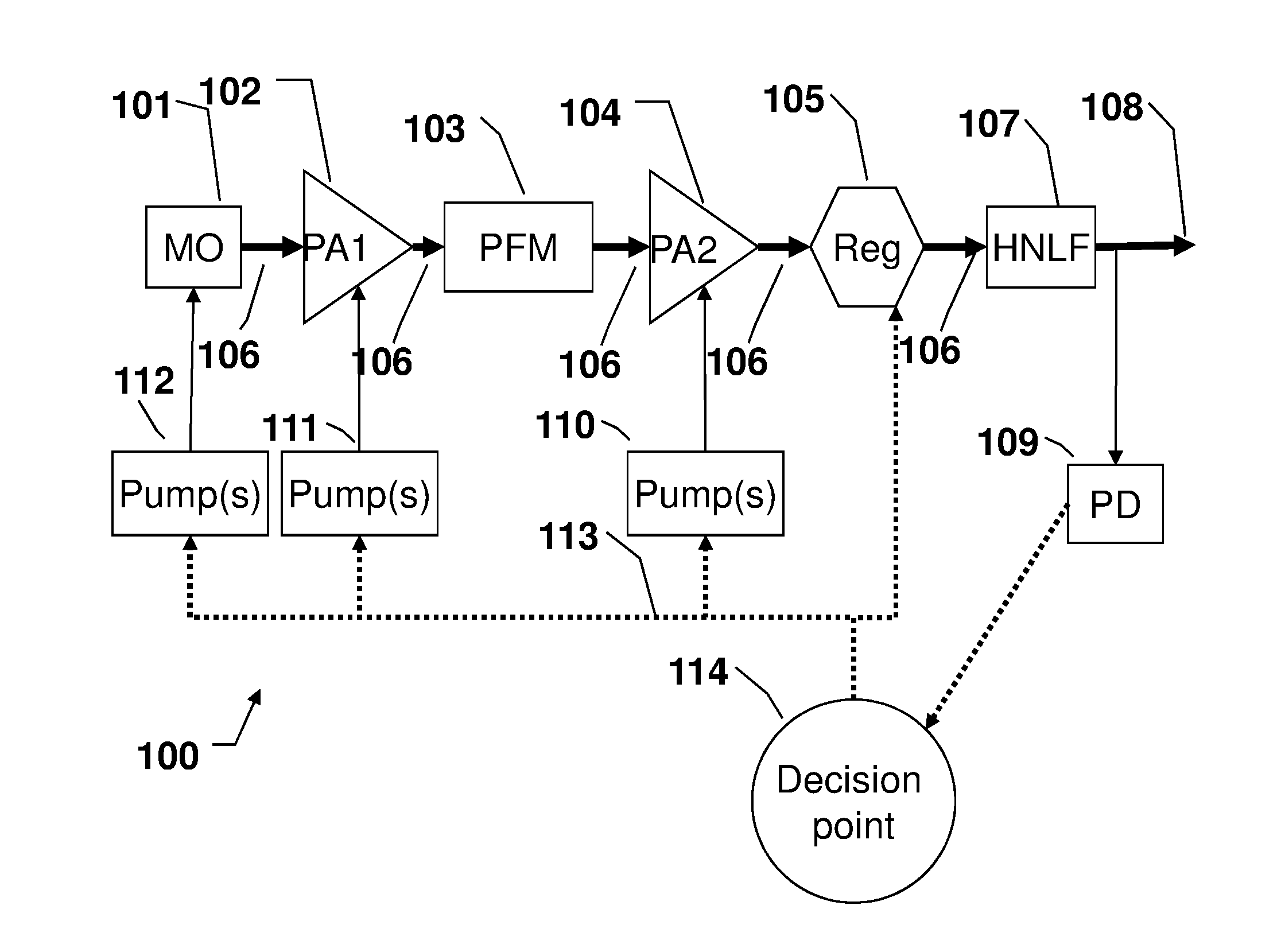
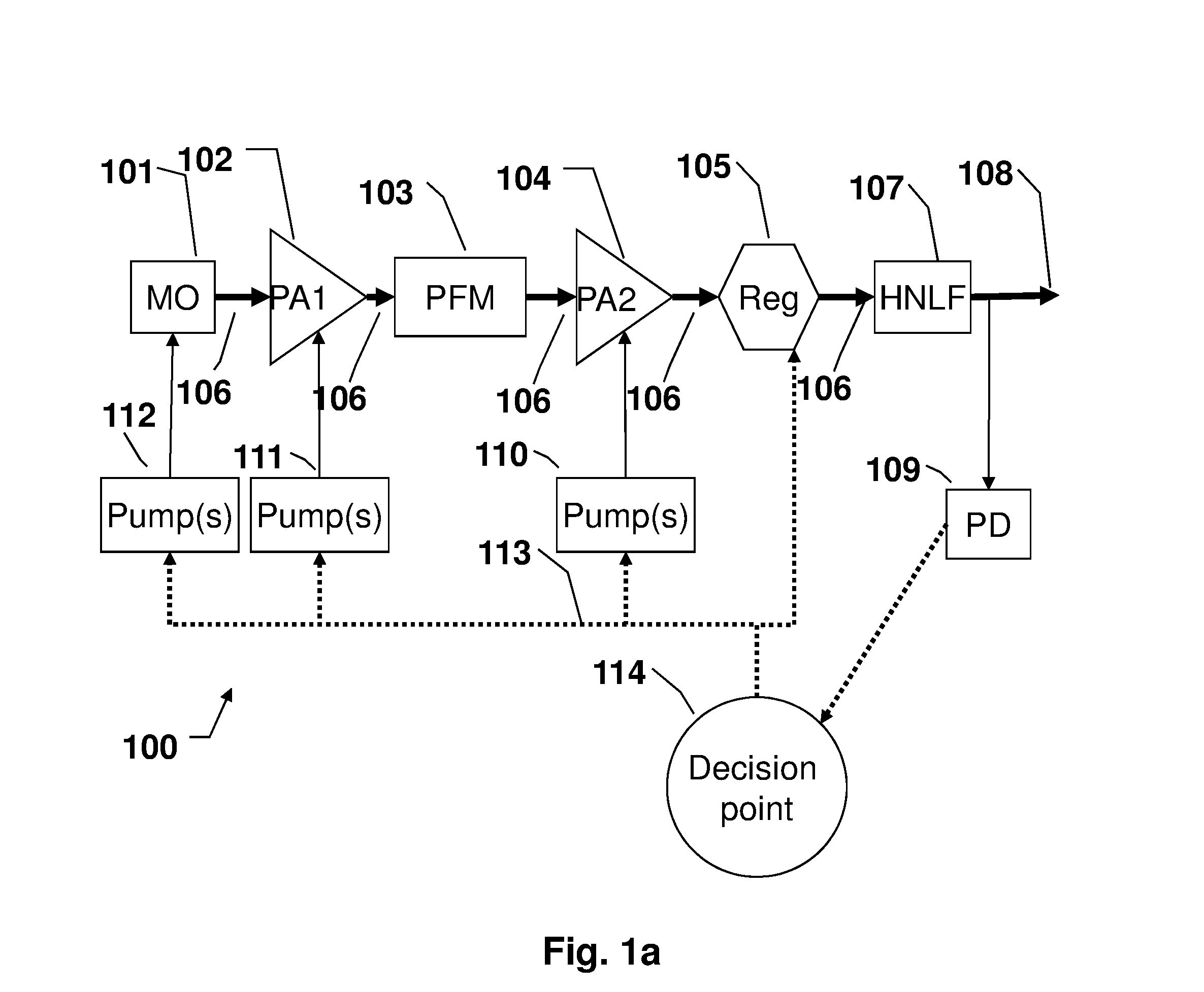
[0072]FIG. 1a shows a schematic intermediate supercontinuum light source suitable for the present invention.
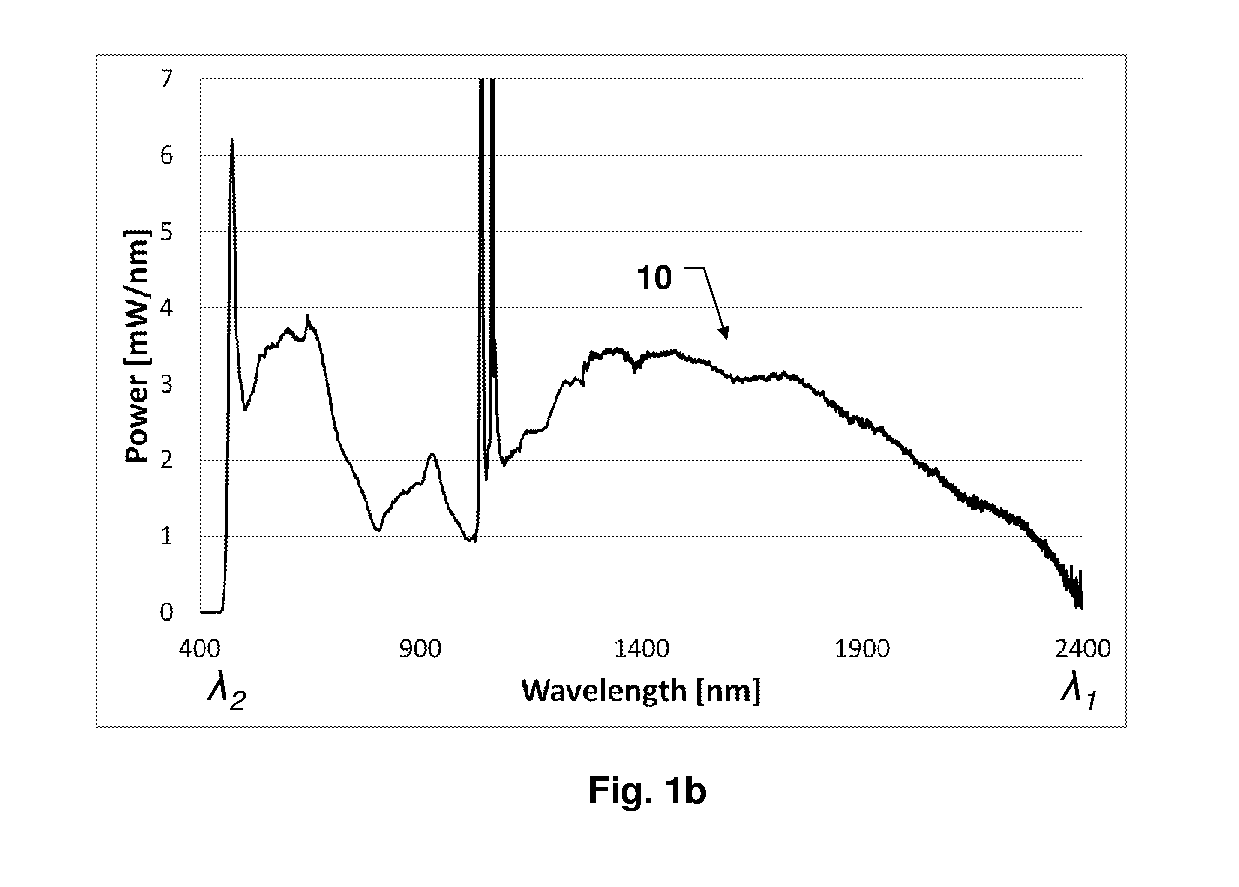
[0073]FIG. 1b shows an example of a supercontinuum spectrum (10) spanning from λ2 being about 460 nm to λ1 being about 2400 nm.
[0074]FIGS. 2a and 2b show examples of pulse frequency modulators (PFM) of an intermediate supercontinuum light source according to the present invention.
[0075]FIG. 3a shows measurement setup suitable for measuring intensity noise in the spectrum of a SC light source, such as that of FIG. 1.
[0076]FIG. 3b shows an example of a supercontinuum spectrum output from the intermediate supercontinuum light source 100, as well as an example of the spectrum output from the single mode coupling unit 300, respectively.
[0077]FIGS. 3c, 3d and 3e show exemplified spectra output from the single mode coupling unit.
[0078]FIGS. 4a and 4b show the average intensity noise of an intermediate supercontinuum light source after and prior to compensation for spectrometer noise....
PUM
 Abstract
Description
Claims
Application Information