Connector and injection method for filler material

Active Publication Date: 2015-05-21
YAZAKI CORP
View PDF4 Cites 5 Cited by
  • Summary
  • Abstract
  • Description
  • Claims
  • Application Information

AI Technical Summary

Benefits of technology

[0026]In contrast, in the connector of the configuration of the above-mentioned (1), a second portion within the inner surface of the connector housing and the outer surface of the filler material opposite to the second portion are released from each other by the release layer composed of releasing material being interposed in contact with and between the second portion and the outer surface of the filler material. Thus, in comparison with a case of absence of the release layer, the extent of constraint on the filler material by the connector housing is alleviated. Thus, in comparison with a case of absence of the release layer, a larger amount of free expansion and free contraction is allowed to the filler material when the ambient temperature of the connector varies. This reduces a thermal stress generated in the filler material and hence suppresses fatigue and degradation in the filler material.
[0027]Further, a thermal shock generated in the filler material is reduced. As a result, generation of cracks in the filler material is suppressed.
[0028]Further, in the connector of the configuration of the above-mentioned (2), the portion where the release layer is formed is located near a portion where the terminals, the electric wires, and the inner plate which have thermal expansion coefficients different from that of the filler material are collected. Thus, in this portion, when those portions adhere to each other in a case of absence of the release layer, a thermal stress is easily generated so that cracks are easily generated. In contrast, in th

Problems solved by technology

Nevertheless, in such a connector of the conventional art, a possibility is present that as the operating time increases, cracks are generated in the epoxy resin serving as the filler material.
Further, when cracks are once generated in the filler material, the cracks may gradually grow in the inside of the filler material as time advances further.
When cracks are generated in the filler material, a possibility arises that, for example, AT oil having crept by a capillary phenomenon the electric wires inserted into the terminal holder and then entered the inside of the connector housing moves through the inside of the cracks so as to exude into the connector fitting chamber so that the liquid-tight property of the connector is lost.
As a result, the filler material becomes fatigued and degraded so that a possibility arises that cracks are generated in the filler material.
Further, as another cause of generation of cracks in the fil

Method used


Image

  • Connector and injection method for filler material
  • Connector and injection method for filler material
  • Connector and injection method for filler material

Examples


Embodiment Construction

(referred to as an “embodiment”, hereinafter) given below is read thoroughly with reference to the accompanying drawings.

BRIEF DESCRIPTION OF THE DRAWINGS

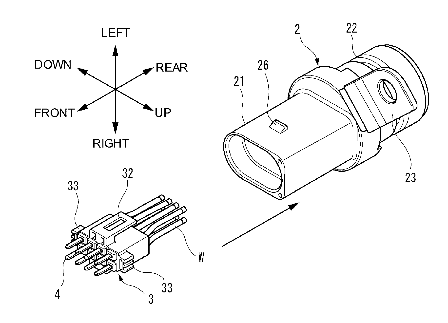
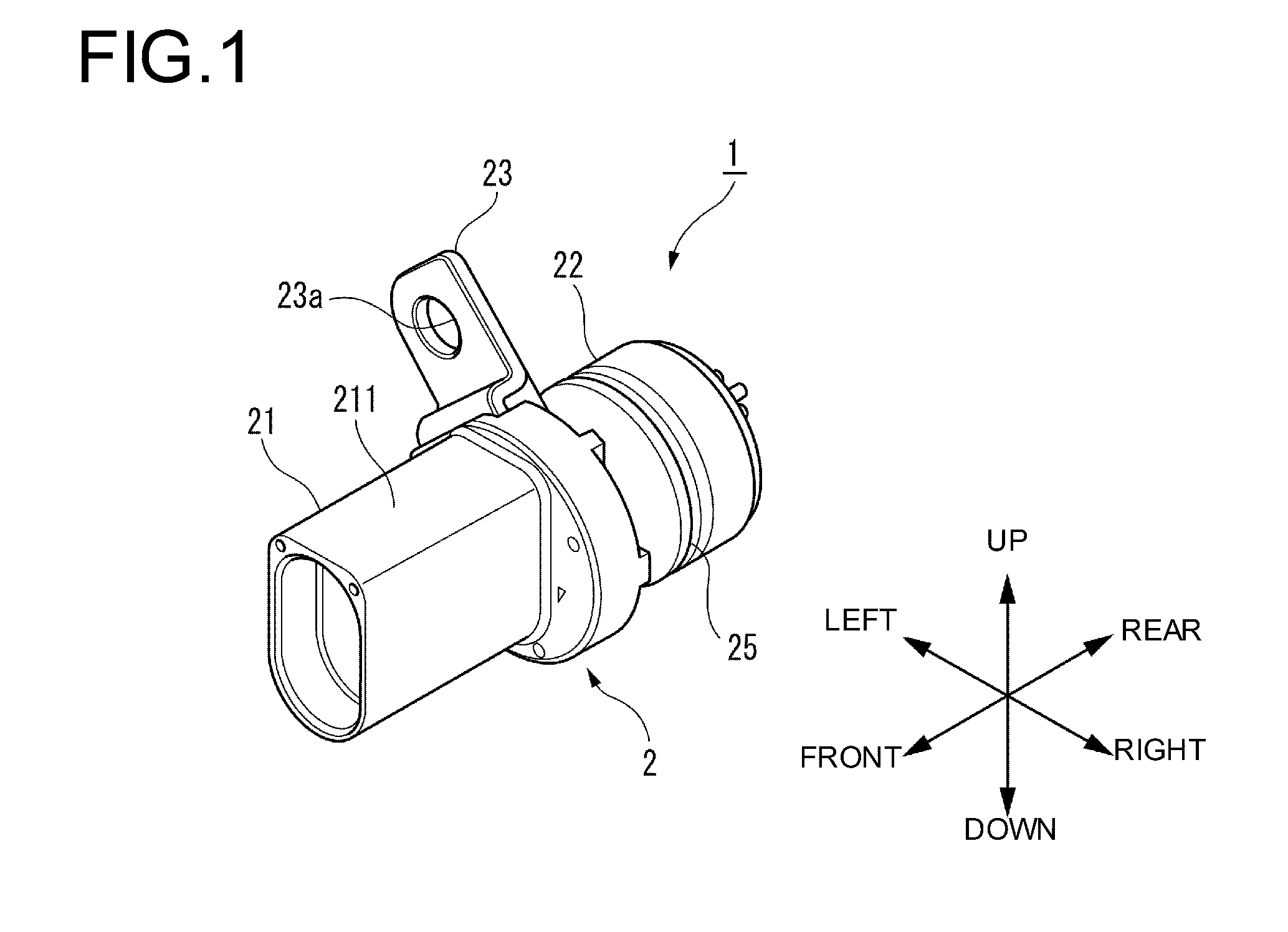
[0033]FIG. 1 is a perspective view showing an external appearance of a connector according to an embodiment of the present invention.

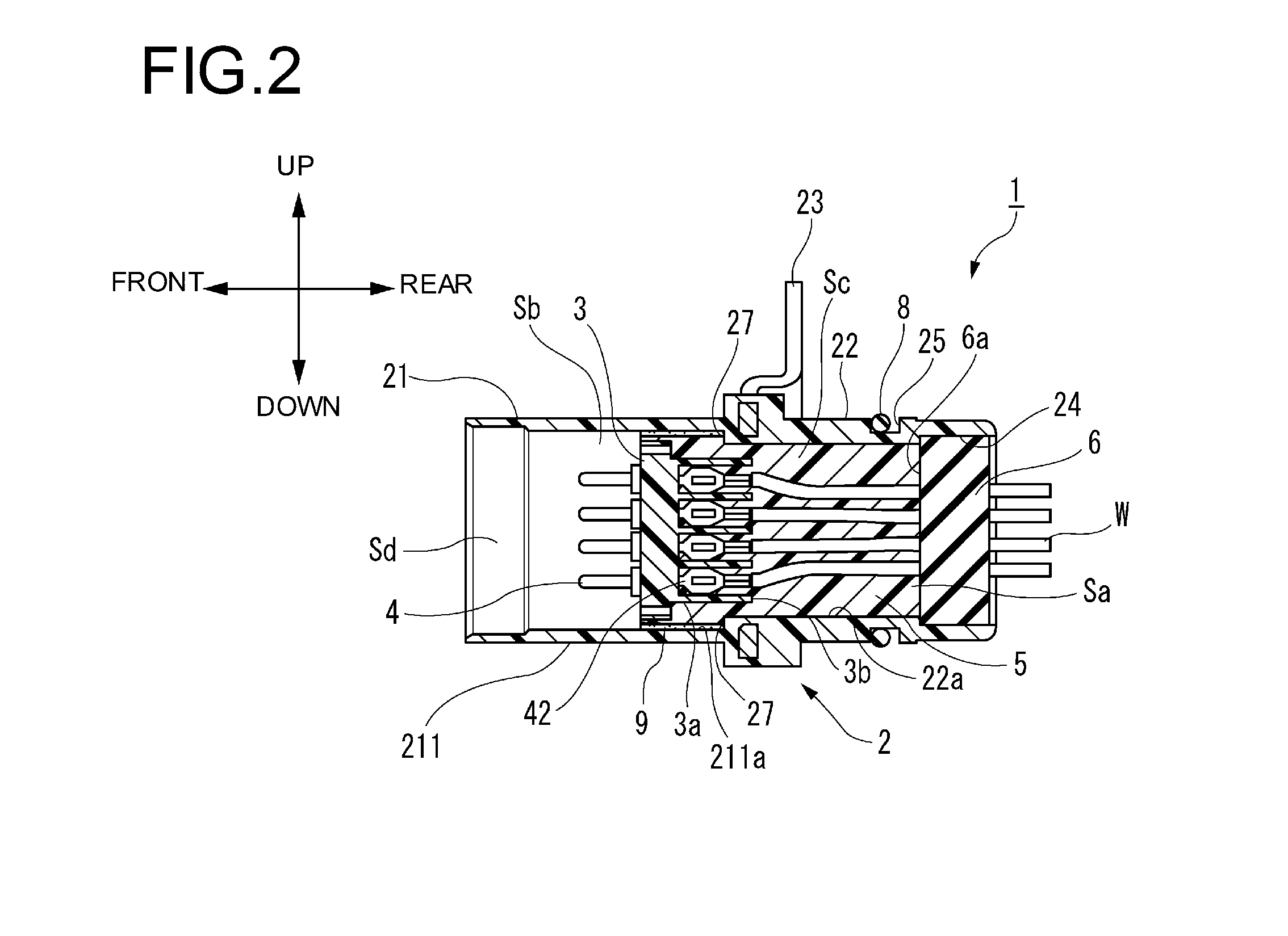
[0034]FIG. 2 is a longitudinal sectional view of a connector of FIG. 1.

[0035]FIG. 3 is a diagram in which a connector of FIG. 1 is viewed from the front side.

[0036]FIG. 4 is a longitudinal sectional view of a connector obtained at a coating step.

[0037]FIG. 5 is a perspective view showing a terminal insertion step of inserting, into an inner plate, terminals to which electric wires are connected by pressure bonding.

[0038]FIG. 6 is a perspective view showing an inner plate insertion step of inserting an inner plate obtained at a terminal insertion step, into a connector housing obtained at a coating step.

[0039]FIG. 7 is a perspective view showing a plug member insertion step of inserting a rubber plug i...


PUM

PropertyMeasurementUnit
Timeaaaaaaaaaa

Abstract

A connector includes a connector housing, an inner plate that supports a terminal connected to a one end portion of an electric wire and that is accommodated in an inside of the connector housing, and filler material that fills the inside of the connector housing which has accommodated the inner plate and that is then hardened so as to cover a connection part of the electric wire and the terminal. The filler material adheres to a first portion within an inner surface of the connector housing and to an outer surface of the inner plate. A release layer is provided between a second portion within the inner surface of the connector housing and an outer surface of the filler material opposite to the second portion.

Description

CROSS REFERENCE TO RELATED APPLICATION[0001]This application is a continuation of PCT application No. PCT / JP2013 / 066219, which was filed on Jun. 12, 2013 based on Japanese Patent Application (No. 2012-140196) filed on Jun. 21, 2012, the contents of which are incorporated herein by reference. Also, all the references cited herein are incorporated as a whole.BACKGROUND[0002]1. Technical Field[0003]The present invention relates to a connector and an injection method for filler material.[0004]2. Background Art[0005]In some connectors, a situation that liquid present in the outside of a connector enters the inside of the connector is required to be avoided, that is, a liquid-tight property is required.[0006]In the conventional art, for the purpose of providing a connector having a high liquid-tight property, connectors having various kinds of structures have been proposed (for example, see JP-A-2002-270283 and JP-A-2012-59652).SUMMARY[0007]For example, the connector disclosed in JP-A-200...

Claims


Application Information

Patent Timeline
IPC IPC(8): H01R13/52H01R43/24H01R43/00
CPCH01R13/5216H01R43/24H01R13/5202H01R43/005H01R13/5205H01R13/502H01R2201/26H01R13/52H01R13/5208H01R13/521H01R13/5213H01R13/5219H01R43/00
Inventor SATO, AKIRATAKAHASHI, KAZUHIDESUZUKI, ETSUROTAKAHASHI, KENJI
Owner YAZAKI CORP
Why Eureka
Try Eureka