RF soi switch with backside cavity and the method to form it
a soi switch and backside cavity technology, applied in the field of integrated circuits having transistors, can solve the problems of affecting performance and large capacitive coupling through the substrate, and achieve the effect of improving the performance of the integrated circuit and improving the radio frequency characteristics
- Summary
- Abstract
- Description
- Claims
- Application Information
AI Technical Summary
Benefits of technology
Problems solved by technology
Method used
Image
Examples
first embodiment
[0027]An integrated circuit includes a transistor disposed on a semiconductor substrate having a cavity disposed below (underneath) the transistor. The transistor can be isolated from the semiconductor substrate through the cavity, and the parasitic coupling between the source, the drain, and the gate of the transistor, and the parasitic capacitive coupling of the semiconductor substrate can be reduced to ultimately improve the performance of the integrated circuit.
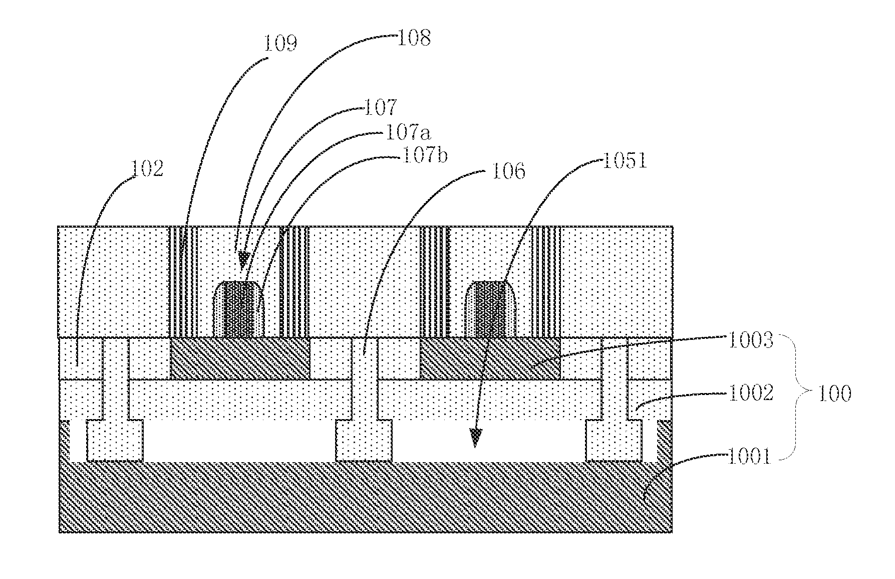
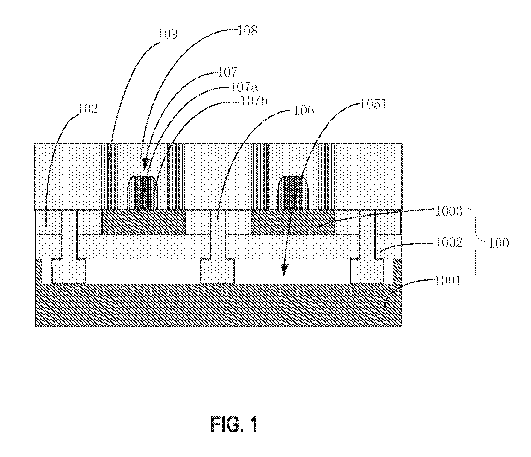
[0028]FIG. 1 is a cross-sectional view of a structure of an integrated circuit according to an embodiment of the present invention. As shown in FIG. 1, the integrated circuit includes a compound semiconductor substrate 100 and a transistor 107 disposed in the compound semiconductor substrate. The compound semiconductor substrate includes a first semiconductor substrate 1001, an insulating layer 1002 on the first semiconductor substrate, and a second semiconductor substrate 1003 on the insulating layer. Transistor 107 is d...
second embodiment
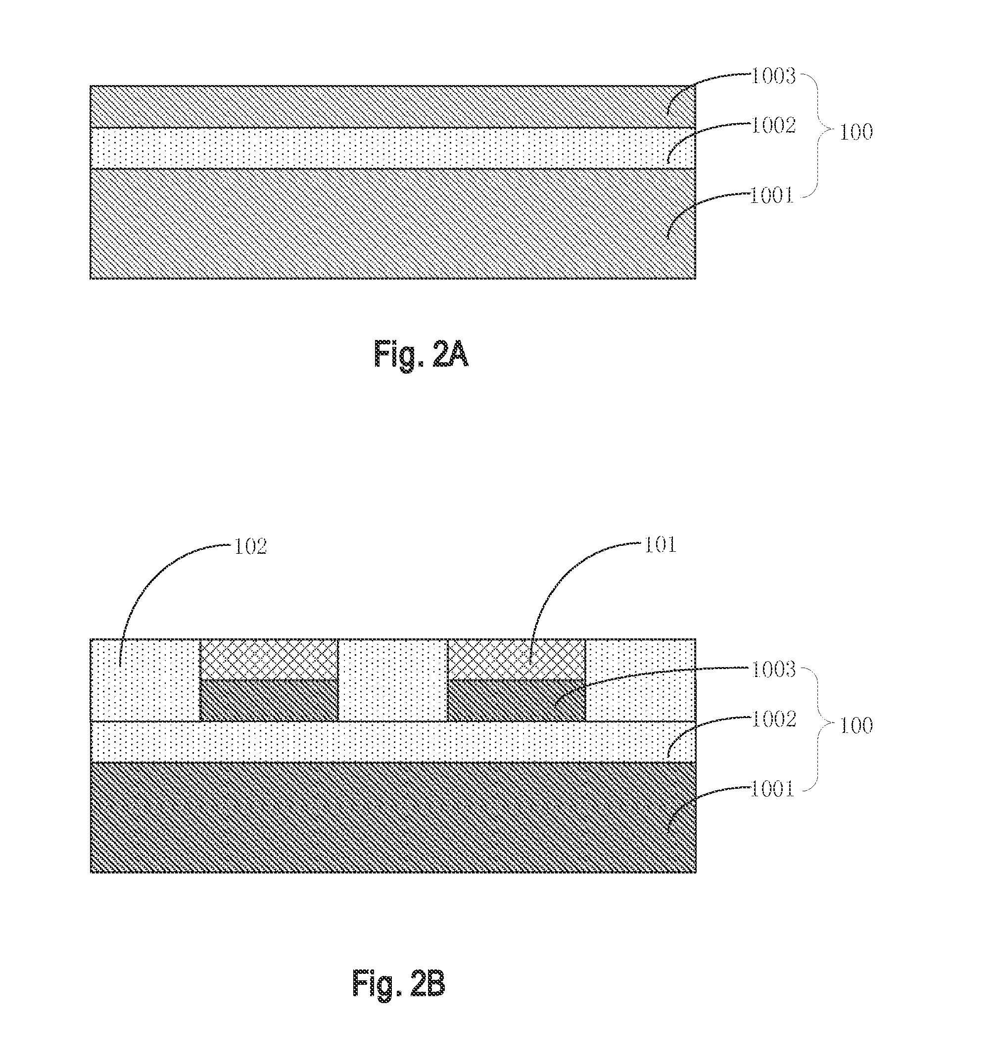
[0043]Referring to FIGS. 2A through 2F and FIG. 3, embodiments of the present invention provide a method of manufacturing an integrated circuit. FIGS. 2A through 2F are cross-sectional views of intermediate stages at different points during a manufacturing method of an integrated circuit, in accordance with an embodiment of the present invention.
[0044]According to an embodiment, a method of manufacturing an integrated circuit may include providing a compound semiconductor substrate having a first semiconductor substrate 1001, an insulating layer 1002 on first semiconductor substrate 1001, and a second semiconductor substrate 1002 on insulating layer 1002, as shown in FIG. 2A.
[0045]First semiconductor substrate 1001 is a silicon layer having a plane orientation (111), and second semiconductor substrate 1003 is a silicon layer having a plane orientation (111).
[0046]Insulating layer 1002 can be an oxide layer or a layer comprising any suitable insulating materials.
[0047]Because of the ...
third embodiment
[0074]Embodiments of the present invention also provide an electronic device. The electronic device includes the above-described integration circuit that is manufactured according to the method described above.
[0075]Because the integrated circuit has a cavity disposed below the transistor, coupling between the drain, source and gate of the transistor and between the semiconductor substrate can be significantly reduced to improve the performance of the electronic device. The integrated circuit according to embodiments of the present invention can be embedded in electronic devices that have a broad range of applications, such as, but not limited to, cellular phones, tablet PCs, netbooks, game consoles, portable DVD players, portable navigation systems, still and video cameras, digital voice recorders, MP3, MP4, and other electronic products.
PUM
 Abstract
Description
Claims
Application Information
 - R&D
- Intellectual Property
- Life Sciences
- Materials
- Tech Scout
- Unparalleled Data Quality
- Higher Quality Content
- 60% Fewer Hallucinations
Browse by: Latest US Patents, China's latest patents, Technical Efficacy Thesaurus, Application Domain, Technology Topic, Popular Technical Reports.
© 2025 PatSnap. All rights reserved.Legal|Privacy policy|Modern Slavery Act Transparency Statement|Sitemap|About US| Contact US: help@patsnap.com


