Disposable world-to-chip interface for digital microfluidics

a technology of microfluidics and world-to-chip interface, which is applied in the field of disassembly of world-to-chip interface for digital microfluidics, can solve the problems of requiring a large system size and surrounding apparatus, requiring much more space, and requiring more space, so as to achieve less skill in operation, eliminate human error, and facilitate use

Active Publication Date: 2015-05-28
RGT UNIV OF CALIFORNIA
View PDF4 Cites 14 Cited by
  • Summary
  • Abstract
  • Description
  • Claims
  • Application Information

AI Technical Summary

Benefits of technology

[0012]Although chemistry on digital microfluidics has been performed using manual interfacing (e.g. pipetting) with the chip for preparation, loading and collection operations, embodiments incorporating features of the present invention describe a compact, automated, integrated platform that interfaces with the chip upstream and downstream of the reaction, as well as between intermediate reaction steps if needed. Some embodiments utilize no active wetted components in this interface allowing a single-use disposable cassette based system which does not require any wash steps between reactions.
[0013]A significant advantage of the invention is its automation. As a result of automation, the platform (to carry out microscale chemical reactions, for example) is easier to use, requires less skill to operate, and human error is eliminated. Furthermore, repeatability of processes is increased. Additionally, if the chemical process involves hazardous or sensitive reagents or reactions (e.g. radioactive isotopes), it can be placed in an appropriate shielding or containment without hindering operation as would foe the case for a manually operated system.

Problems solved by technology

However, this system utilized liquid valves, which resulted in the system being more expensive, the fluid path requiring cleaning rather than being disposable, and required the system to have larger size and larger surrounding apparatus.
Commercially available rotary valves with small volume injection loops have been used to achieve similar results to the above system, but still require much more space, undercutting the benefits of the microfluidics in the rest of the chemical processing system.
Furthermore, these systems, however do not interface digital microfluidics chips, do not utilise electrowetting with solvent exchange, and do not utilize an integrated platform for digital microfluidics or a purely liquid-valve free system.
Reagents utilized with the above mentioned systems are typically loaded manually to the chip, leading to chemical and radiation exposure hazards, and require greater time, effort and expertise.
The common approach of pre-loading reagents into on-chip or off chip reservoirs is not feasible for this application due to volatility of many reagents, concerns of cross-contamination, and the possibility of being incompatible with certain organic solvents.
However, one of the disadvantages of these approaches is that they are not suitable for applications where the collected product needs to be further processed for more synthesis steps, purification or quality control before use, as is commonly required from chemical synthesis products, especially those for use in biological systems.

Method used


Image

  • Disposable world-to-chip interface for digital microfluidics
  • Disposable world-to-chip interface for digital microfluidics
  • Disposable world-to-chip interface for digital microfluidics

Examples


Embodiment Construction

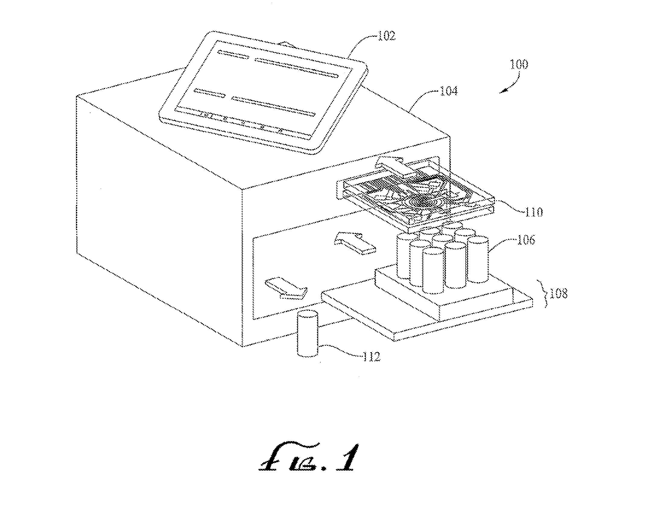
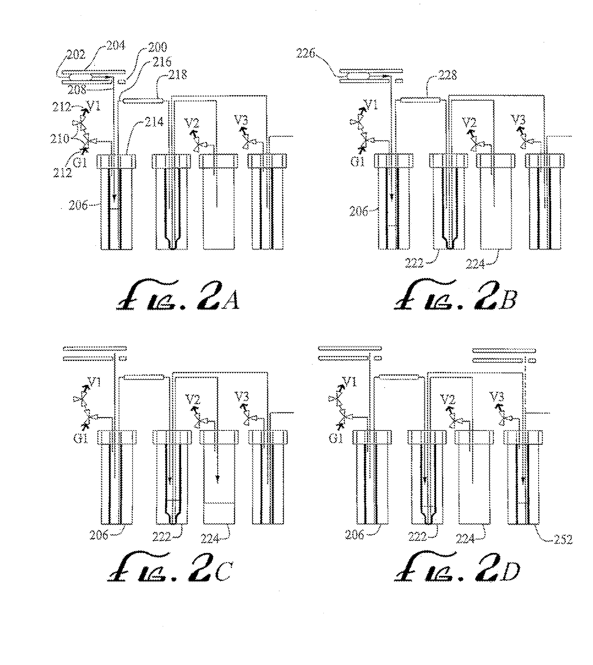
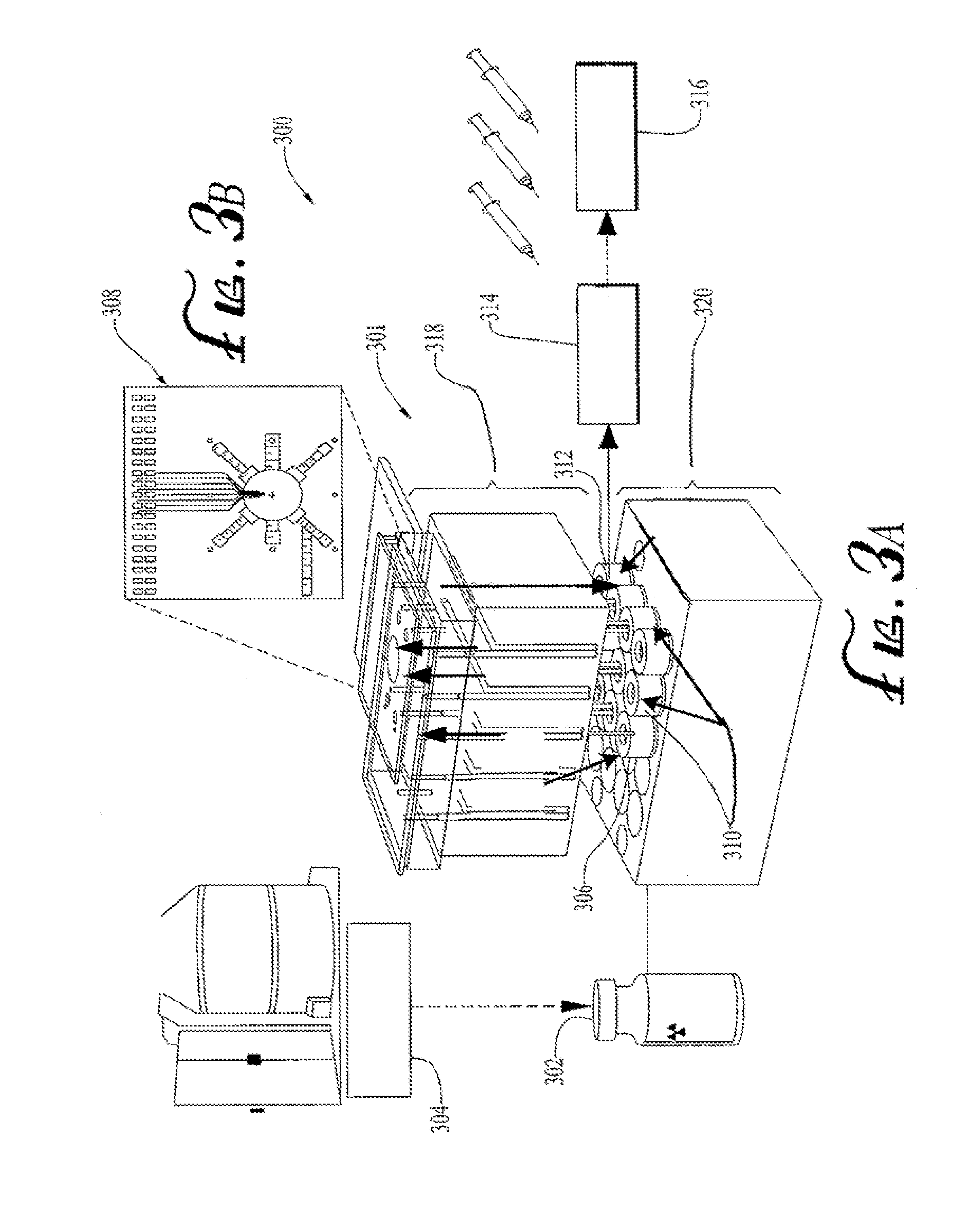
[0042]In some embodiments incorporating features of the present invention, compact, automated, integrated platforms were utilized that interface with a chip upstream and downstream of the reaction, as well as between intermediate reaction steps if needed. In the various embodiments disclosed many different arrangements are possible which provide automated operation of the interface, including automation of a multiple reagent process.

[0043]Throughout this disclosure, the preferred embodiments herein and examples illustrated are provided as exemplars, rather than as limitations on the scope of the present disclosure. As used herein, the terms “invention,”“method,”“system,”“present method,”“present system” or “present invention” refers to any one of the embodiments incorporating features of the invention described herein, and any equivalents. Furthermore, reference to various feature(s) of the “invention,”“method,”“system,”“present method,”“present system,” or “present invention” throu...


PUM


Abstract

The present disclosure sets forth incorporating microfluidic chips Interfaces for use with digital microfluidic processes. Methods and devices according to the present disclosure utilize compact, integrated platforms that interface with a chip upstream and downstream of the reaction, as well as between intermediate reaction steps if needed. In some embodiments these interfaces are automated, including automation of a multiple reagent process. Various reagent delivery systems and methods are also disclosed.

Description

CROSS REFERENCE TO RELATED APPLICATIONS[0001]This application claims the benefit of U.S. Provisional Application Ser. No. 61 / 657,570, to Gaurav Shah, et al., entitled Disposable World-To-Chip Interface for Digital Micro fluidics, filed on Jun. 8, 2012, which is hereby incorporated herein in its entirety by reference, including the drawings, cables charts, schematics, diagrams and related written description.STATEMENT REGARDING FEDERALLY SPONSORED RESEARCH AND DEVELOPMENT[0002]This invention was made with Government support of Grant Nos. DE-SC0001249 and DE-SC0005056, awarded by the U.S. Department of Energy. The Government has certain rights in this invention.BACKGROUND OF THE INVENTION[0003]1. Field of the Invention[0004]The present disclosure relates to a system, for example an automated system, for interfacing, processing, preparing, delivering to and / or collection of products from a micro-processing chip.[0005]2. Description of the Related Art[0006]A system performing sample pre...

Claims


Application Information

Patent Timeline
Patent Type & Authority Applications(United States)
IPC IPC(8): B01L3/00
CPCB01L3/502753G01N35/10B01L3/502715B01L2200/027B01L2200/0673B01L2300/0681B01L2400/0487B01L2400/0622G01N2035/00158G01N2035/1034
Inventor VAN DAM, R. MICHAELSHAH, GAURAVKENG, PEI-YUIN
Owner RGT UNIV OF CALIFORNIA
Why Eureka
Try Eureka