Phosphor material and light-emitting device

Active Publication Date: 2015-06-04
PANASONIC INTELLECTUAL PROPERTY MANAGEMENT CO LTD
View PDF3 Cites 4 Cited by
  • Summary
  • Abstract
  • Description
  • Claims
  • Application Information

AI Technical Summary

Benefits of technology

[0012]According to an embodiment of the present disclosure, a phosphor material having high luminous efficiency and excellent temperature character

Problems solved by technology

However, conventional red phosphors do not have sufficient luminous efficiency.
Therefore, there is a big problem i

Method used


Image

  • Phosphor material and light-emitting device
  • Phosphor material and light-emitting device
  • Phosphor material and light-emitting device

Examples


first embodiment

[0018]A phosphor material according to a first embodiment of the present disclosure contains a major component represented by the formula A2-v-w-x-yBvLnwEuxSmyM2-zDzO8, where A is one or more elements selected from the group consisting of alkaline-earth metal elements; B is one or more elements selected from the group consisting of alkali metal elements; Ln is one or more elements selected from the group consisting of rare-earth elements other than Eu and Sm; M is one or more elements selected from the group consisting of W and Mo; D is one or more elements selected from the group consisting of Nb and Ta; and v, w, x, y, and z satisfy the inequalities 0≦v≦0.5, 0.15≦x+y≦0.7, 0≦y≦0.05, and 0

[0019]The weight ratio of the major component to the phosphor material may be 90% or more. Alternatively, the weight ratio of the major component to the phosphor material may be 95% or more.

[0020]The phosphor material according to this embodiment has an emission sp...

second embodiment

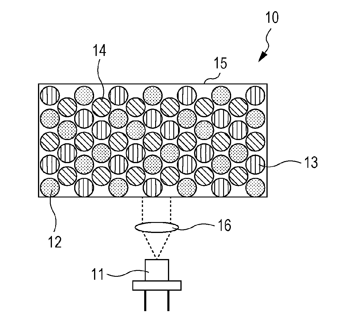
[0042]A second embodiment of the present disclosure provides a light-emitting device including at least an excitation light source and a phosphor material that absorbs excitation light emitted from the excitation light source to emit light. The phosphor material used in this embodiment is that described in the first embodiment. A example of the light-emitting device includes a projector light source, a vehicle headlamp light source, or a white LED illumination light source. LED or a combination of LD and a phosphor is included in the light-emitting device.

[0043]The light-emitting device according to this embodiment further includes a semiconductor light-emitting element emitting light with a peak wavelength of, for example, 380 nm to 470 nm. The phosphor material absorbs a portion of the light emitted from the semiconductor light-emitting element to emit red light. In this embodiment, the semiconductor light-emitting element includes an emitting layer made of, for example, a gallium...

example 1

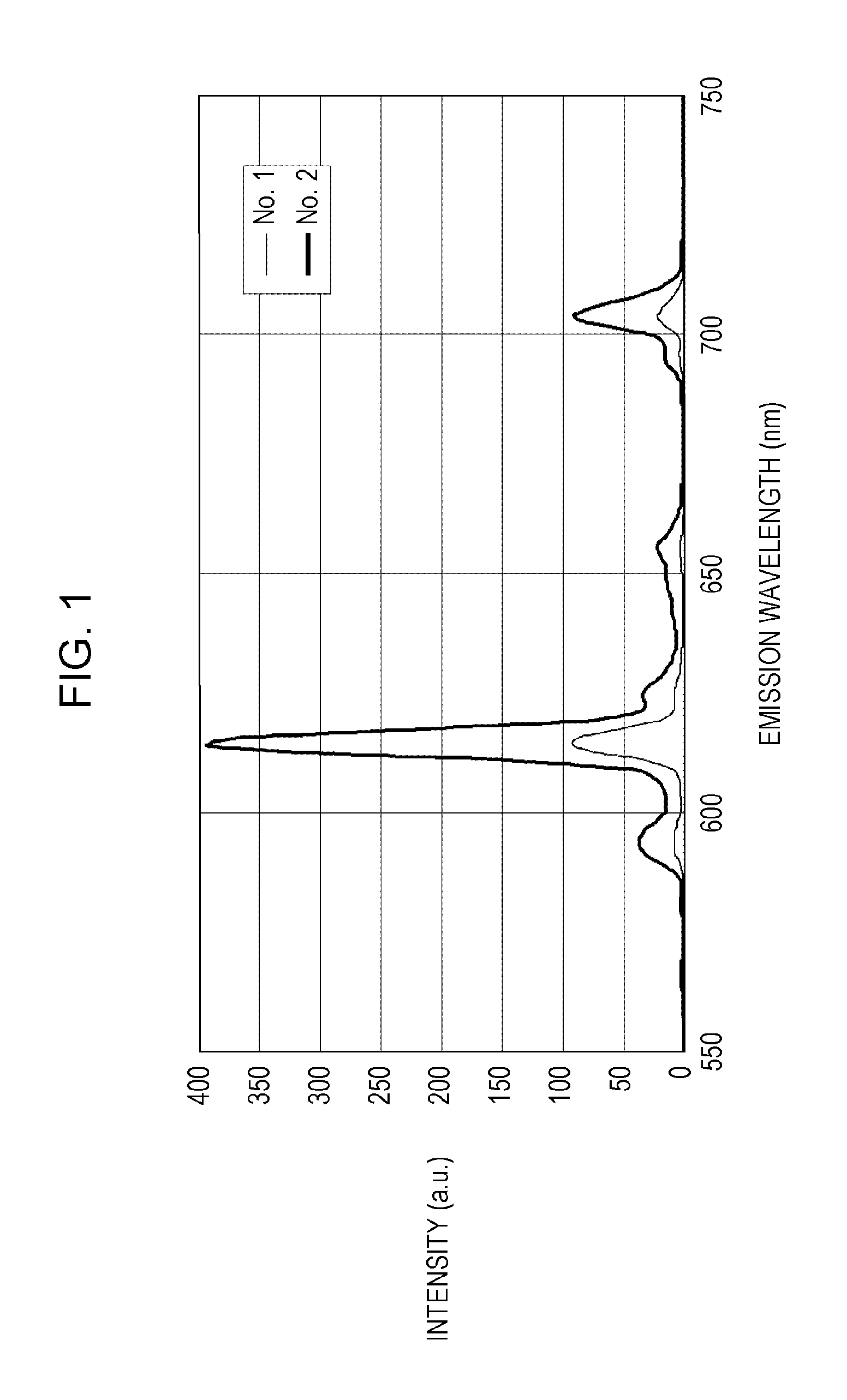
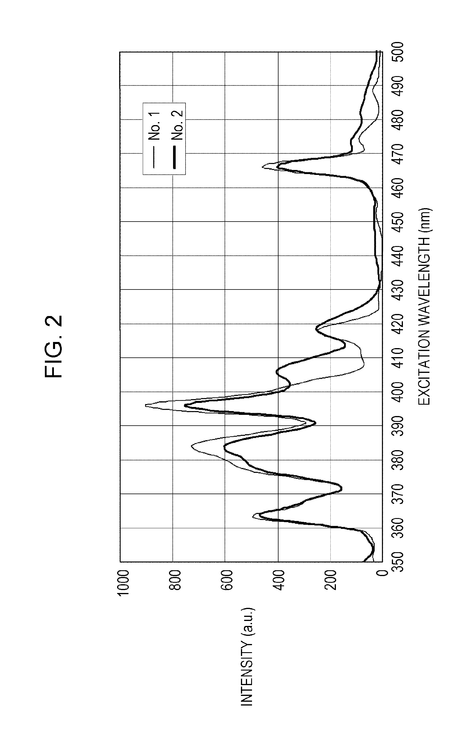
[0047]Table 1 shows the compositions of Samples 1 and 2 which are examples of the present disclosure. In Example 1, each sample in Table 1 corresponds to its number and therefore, for example, Sample No. 1 is described as Sample 1. Incidentally, Samples 1 and 2 correspond to examples and therefore are described as “E” in the item “Judgment” in Table 1.

[0048]The compositions of Samples 1 and 2 are represented by the formula A2-v-w-x-yBvLnwEuxSmyM2-zDzO8. Elements shown in Table 1 were used as A, B, Ln, M, D, and an additive. Each value represents the composition ratio. Powders of CaCO3, Li2CO3, Gd2O3, Eu2O3, Sm2O3, WO3, and Nb2O5 corresponding to a special grade or higher grade chemical were used as starting materials to produce Samples 1 and 2. The raw material powders were weighed such that the composition ratio of each of Ca, Li, Gd, Eu, Sm, W, and Nb was as shown in Table 1. The weight obtained by subtracting the weight of CO2 eliminated by firing from the total thereof was deter...


PUM


Abstract

A phosphor material according to an embodiment of the present disclosure contains a major component represented by the formula A2-v-w-x-yBvLnwEuxSmyM2-zDzO8, where A is one or more elements selected from the group consisting of alkaline-earth metal elements; B is one or more elements selected from the group consisting of alkali metal elements; Ln is one or more elements selected from the group consisting of rare-earth elements other than Eu and Sm; M is one or more elements selected from the group consisting of W and Mo; D is one or more elements selected from the group consisting of Nb and Ta; and v, w, x, y, and z satisfy the inequalities 0≦v≦0.5, 0.15≦x+y≦0.7, 0≦y≦0.05, and 0<z≦1.7 and the equation w+x+y=v+z.

Description

CROSS REFERENCES TO RELATED APPLICATIONS[0001]This application claims priority to Japanese Patent Application No. 2013-249803, filed on Dec. 3, 2013, the contents of which are hereby incorporated by reference.BACKGROUND[0002]1. Technical Field[0003]The present disclosure relates to a phosphor material which is combined with a light-emitting device such as a light-emitting diode (hereinafter referred to as “LED”) and a semiconductor laser diode (hereinafter referred to as “LD”) and which can be used in a light-emitting device such as a projector light source, a vehicle headlamp light source, and a white LED illumination light source. Furthermore, the present disclosure relates to a light-emitting device including the phosphor material.[0004]2. Description of the Related Art[0005]A illumination system including a white LED has higher efficiency and longer life as compared to a conventional illumination system and is widely used for business and home from the viewpoint of resource-savi...

Claims


Application Information

Patent Timeline
IPC IPC(8): C09K11/77H01L33/50
CPCH01L33/502C09K11/7794
Inventor INOUE, OSAMUOKUYAMA, KOJIRONITTA, MITSURUSHIRAISHI, SEIGO
Owner PANASONIC INTELLECTUAL PROPERTY MANAGEMENT CO LTD
Why Eureka
Try Eureka