True random number generator

Active Publication Date: 2015-06-04
RGT UNIV OF MICHIGAN
View PDF2 Cites 28 Cited by
  • Summary
  • Abstract
  • Description
  • Claims
  • Application Information

AI Technical Summary

Benefits of technology

[0022]It is possible to map the collapse time value directly to a random number value. However, as the collapse time value is dependent on thermal noise which will tend to exhibit a normal distribution, the collapse time value will take some numeric values more frequently than others. To produce a random number with a uniform probability distribution, the random number value may be determined based on a subset of bits of the collapse time value measured by the time measuring circuit. For example, the collapse time value may be truncated to generate a truncated value corresponding to a number of least significant bits of the collapse time value, and then the random number value may be determined based on the truncated value. The probability distribution with which the least significant bits of the collapse time value take different numeric values tends to be more uniform than the probability distribution for the collapse time value as a whole, and so truncating the collapse time value can improve the randomness of TRNG.
[0023]In some examples, it may also be desirable to exclude the least significant bit of the truncated value when determining the random number value. This can be useful to eliminate sensitivity of the random numbe

Problems solved by technology

However, for other applications the true randomness generated by a TRNG is essential and a PRNG may not be sufficient.
However, analog designs suffer from variation and noise, making them difficult to integrate with digital circuits.
Recent metastability-based methods provide excellent performance but often require careful calibration to remove bias.
SiN MOSFETs exploit larger thermal noise but require post-processing to achieve sufficient randomness.
An oxide breakdown-based TRNG shows high entropy but suffers from low performance and high energy/bit.
In addition, the majority of previous methods cannot pass all NIST (National Institute of Standards and Technology) randomness tests.
The first mode of oscillation may be unstable and so after a period of time the ring oscillator may

Method used


Image

  • True random number generator
  • True random number generator
  • True random number generator

Examples


Embodiment Construction

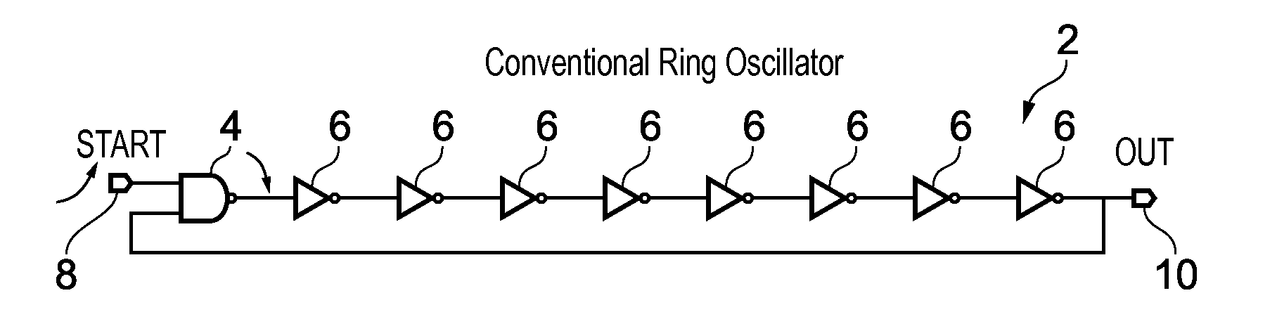
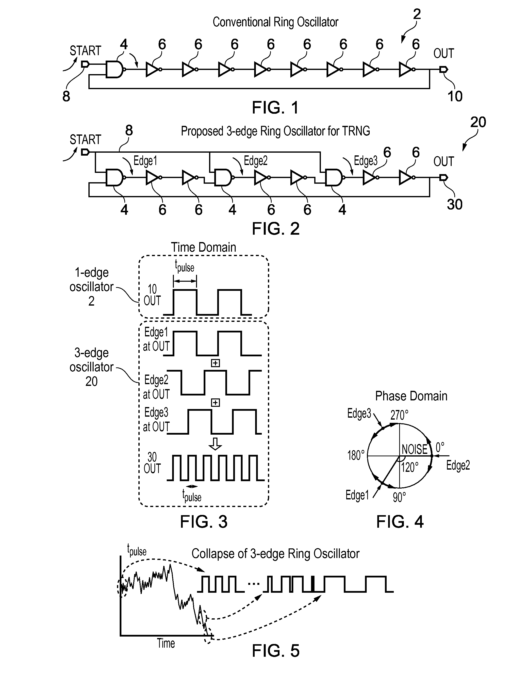
[0048]FIG. 1 illustrates a conventional ring oscillator 2 having an odd number of inverter stages 4, 6. One of the inverter stages is an input inverter stage 4 in the form of a NAND gate which receives an output of an earlier inverter stage 6 and a start signal 8. After a reset of the oscillator 2, both inputs of the NAND gate 4 are at logical 0 and so the output of the NAND gate is at logical 1. When the start signal 8 rises to logical 1 then the NAND gate 4 falls down and this injects an edge into the ring oscillator which then propagates around the ring oscillator. As each inverter stage 6 has an associated delay then the edge takes some time to propagate around the ring. As there is an odd number of inverter stages, the signal at an output node 10 appears as a series of pulses having a given oscillator frequency, as shown in the top part of FIG. 3.

[0049]FIG. 2 illustrates a ring oscillator 20 according to the present technique. Unlike the conventional ring oscillator, in the rin...


PUM


Abstract

A true random number generator comprises a ring oscillator which is triggered to start oscillating in a first mode of oscillation at an oscillation start time. The first mode of oscillation will eventually collapse to a second mode of oscillation dependent on thermal noise. A collapse time from the oscillation start time to the time at which the oscillator collapses to the second mode is measured, and this can be used to determine a random number. The TRNG can be synthesized entirely using standard digital techniques and is able to provide high randomness, good throughput and energy efficiency.

Description

TECHNICAL FIELD[0001]The present technique relates to the field of true random number generators.TECHNICAL BACKGROUND[0002]A true random number generator (TRNG) measures random numbers based on a physical phenomenon that is expected to be random, such as atmospheric noise, thermal noise, or radioactive decay for example Since the physical phenomenon used as the entropy source for the TRNG is unpredictable, the generated random numbers are truly random. This contrasts with pseudo random number generators (PRNGs), which use mathematical formulae or precalculated tables of random numbers to produce sequences of numbers that appear random, but are actually predictable and deterministic given the initial seed condition used to generate the pseudo random numbers. For many applications, PRNGs are sufficient and these may typically be implemented more cheaply than a TRNG. However, for other applications the true randomness generated by a TRNG is essential and a PRNG may not be sufficient.[0...

Claims


Application Information

Patent Timeline
IPC IPC(8): G06F7/58H03K3/03
CPCH03K3/0315G06F7/588H03K3/84
Inventor YANG, KAIYUANSYLVESTER, DENNIS MICHAELBLAAUW, DAVID THEODOREFICK, DAVID ALANHENRY, MICHAEL B.LEE, YOONMYUNG
Owner RGT UNIV OF MICHIGAN
Why Eureka
Try Eureka