Light source unit and photoacoustic measurement apparatus using the same

a light source unit and photoacoustic measurement technology, applied in the direction of point-like light sources, vibration measurement in fluids, solids vibration measurement, etc., can solve the problems of reducing transmission efficiency and unstable energy to be transmitted, so as to improve the distribution of propagation angles, prevent damage to optical fibers, and transmit light more efficiently and stably

Active Publication Date: 2015-06-11
FUJIFILM CORP
View PDF3 Cites 9 Cited by
  • Summary
  • Abstract
  • Description
  • Claims
  • Application Information

AI Technical Summary

Benefits of technology

[0009]The invention has been made in consideration of the above-mentioned problems, and an object of the invention is to provide a light source unit that can more stably and efficiently transmit light in a housing of the light source unit and a photoacoustic measurement apparatus using the light source unit.
[0025]The light source unit and the photoacoustic measurement apparatus according to the invention transmit light to the connector receiving portion in the housing by using the optical fiber. Accordingly, even though the inside of the housing and the housing wall move in different manners with a temperature change and vibration, it is possible to prevent the incident position of light, which is incident on the connector receiving portion, from being shifted. In addition, the light source unit and the photoacoustic measurement apparatus according to the invention increase the distribution of a propagation angle of light flux, which is included in a laser beam, by allowing the laser beam to pass through the diffuser once, and control a beam diameter of the laser beam incident on the optical fiber, by using the focal length of the condensing lens system. Accordingly, when condensing a laser beam by the condensing lens system and allowing the laser beam to be incident on the optical fiber, the light source unit and the photoacoustic measurement apparatus can prevent the laser beam from being excessively narrowed. Therefore, it is possible to prevent damage to the optical fiber that is caused when local light energy exceeds the damage threshold energy of the optical fiber. As a result, it is possible to more stably and efficiently transmit light in the housing of the light source unit.
[0026]Moreover, while a laser beam is transmitted through the optical fiber, the energy profile of the laser beam is made uniform. Accordingly, an effect of uniformly transmitting light to the light guide part of the probe is also obtained.

Problems solved by technology

For this reason, there are problems in that the amount of energy to be transmitted may not be stable and transmission efficiency may be lowered.

Method used


Image

  • Light source unit and photoacoustic measurement apparatus using the same
  • Light source unit and photoacoustic measurement apparatus using the same
  • Light source unit and photoacoustic measurement apparatus using the same

Examples


first embodiment

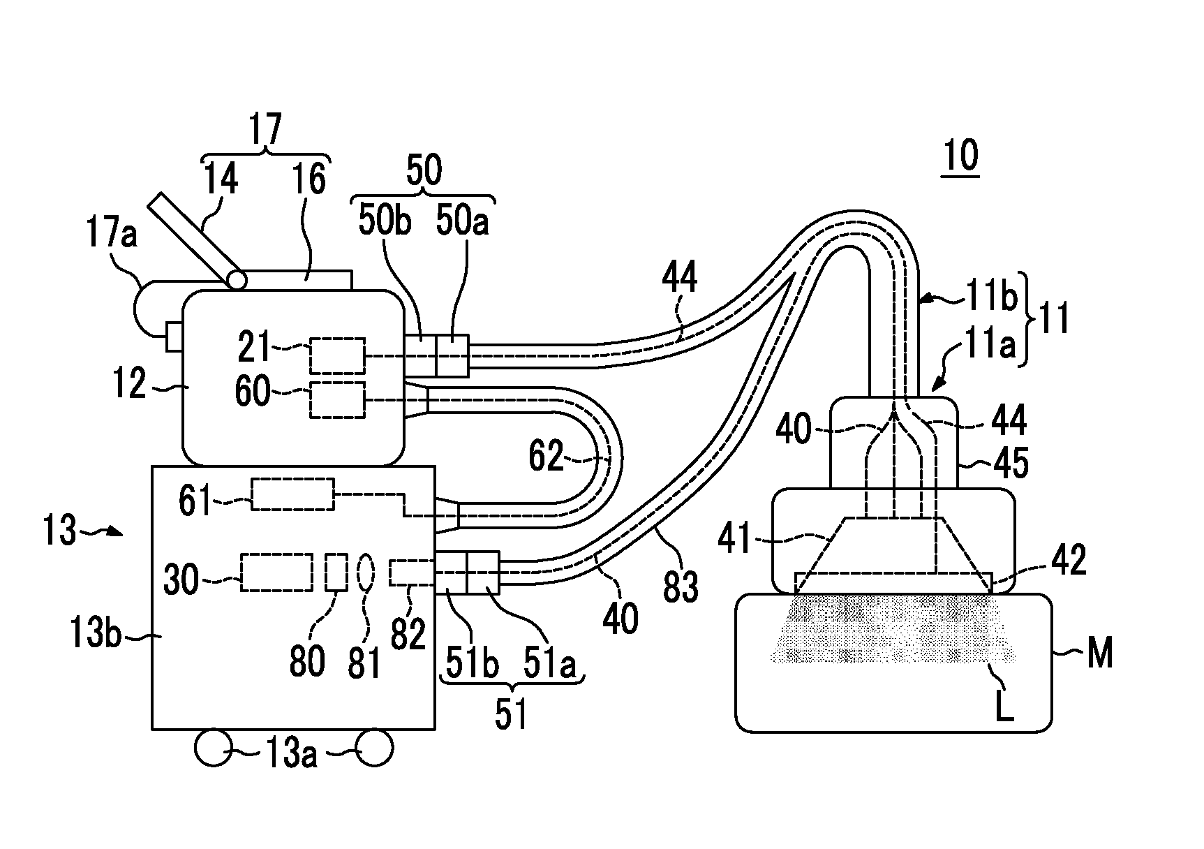
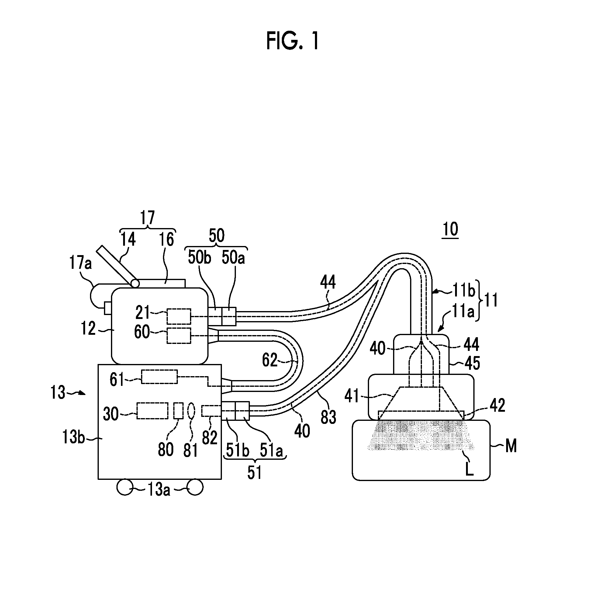
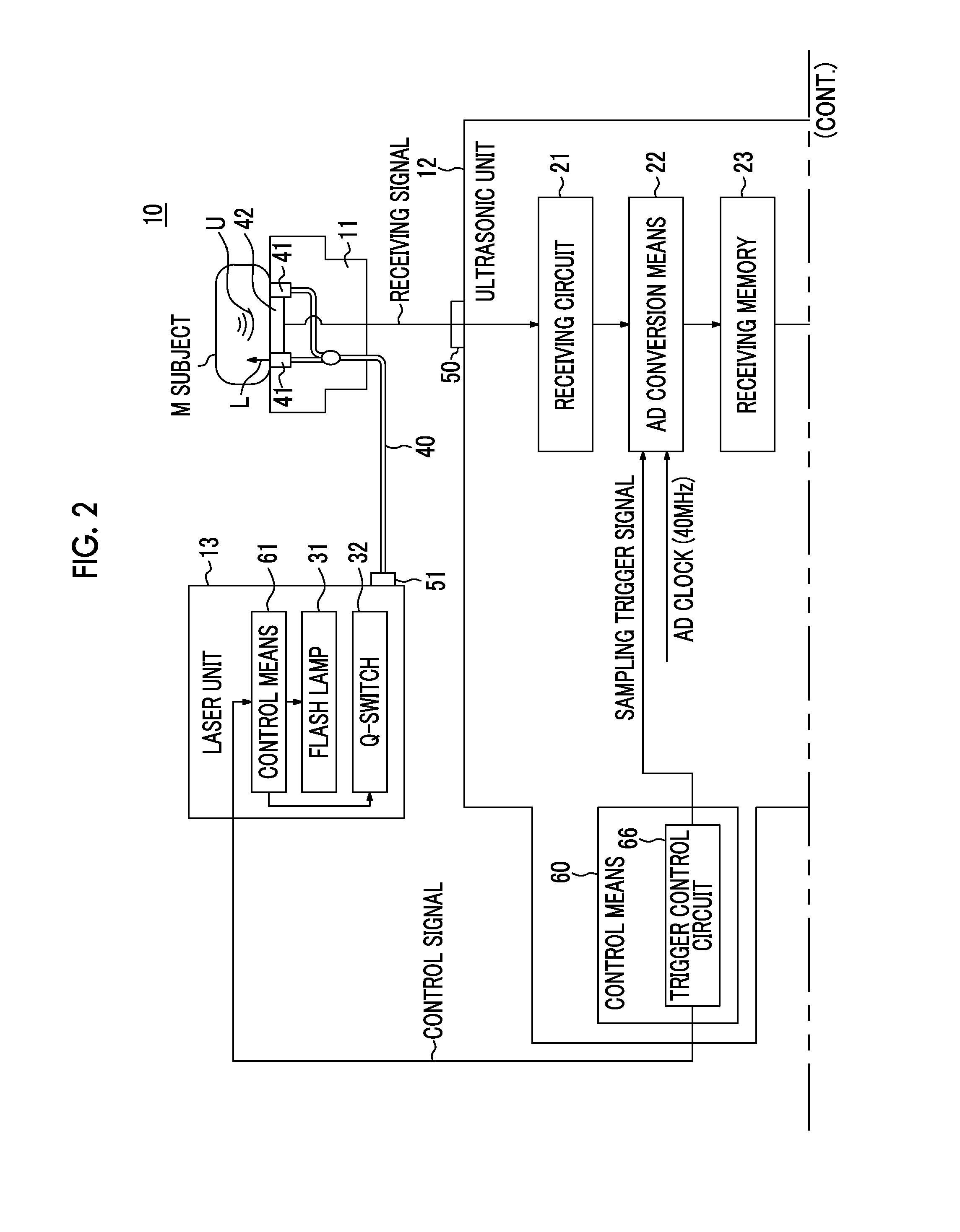
[0048]FIG. 1 is a schematic view showing the configuration of a photoacoustic measurement apparatus of a first embodiment, and FIG. 2 is a block diagram showing the internal configuration of the photoacoustic measurement apparatus of the first embodiment. Further, FIG. 3 is a schematic view showing the configuration of a part of the inside of a unit housing. Meanwhile, in this embodiment, the photoacoustic measurement apparatus is a photoacoustic image forming apparatus that forms photoacoustic images on the basis of photoacoustic signals.

[0049]As shown in FIG. 1, the photoacoustic image forming apparatus 10 of this embodiment includes a probe 11, an ultrasonic unit 12, a laser unit 13, and a personal computer (PC) 17. Further, a subject M is irradiated with a beam L, which is emitted from the laser unit 13, through the probe 11 and a photoacoustic wave, which is caused by the irradiation with the beam, is detected by the probe 11.

[0050]

[0051]As shown in FIGS. 1 and 2, the probe 11 ...

second embodiment

[0133]Next, a second embodiment of a photoacoustic measurement apparatus will be described. A case in which the photoacoustic measurement apparatus is a photoacoustic image forming apparatus 10 will be specifically described even in this embodiment. FIG. 19 is a block diagram showing the configuration of the photoacoustic image forming apparatus 10 of this embodiment. This embodiment is different from the first embodiment in terms of the fact that an ultrasonic image is also formed in addition to a photoacoustic image. Accordingly, the detailed description of the same components as the components of the first embodiment will be omitted unless particularly necessary.

[0134]As in the first embodiment, the photoacoustic image forming apparatus 10 of this embodiment includes a probe 11, an ultrasonic unit 12, a laser unit 13, image display means 14, and input means 16 according to the invention.

[0135]

[0136]The ultrasonic unit 12 of this embodiment includes a transmission control circuit ...


PUM

PropertyMeasurementUnit
wavelength regionaaaaaaaaaa
wavelengthsaaaaaaaaaa

Abstract

It is desirable to more stably and efficiently transmit light in a housing of a light source unit. A light source unit 13, which emits a laser beam L to a light guide part 40, includes: a unit housing 13b that includes a connector receiving portion 51b detachably connected to a connector portion 51a; a light source 30 that is installed in the unit housing 13b and outputs the laser beam L; a diffusion part 80 that diffuses the laser beam L output from the light source 30; a condensing lens system 81 that condenses the laser beam L diffused by the diffusion part 80; and an optical fiber 82a that transmits the laser beam L, which is condensed by the condensing lens system 81, to the connector receiving portion 51b. The connector receiving portion 51b optically connects the optical fiber 82a to the light guide part 40.

Description

CROSS-REFERENCE TO RELATED APPLICATIONS[0001]This application is a Continuation of PCT International Application No. PCT / JP2013 / 072134 filed on Aug. 20, 2013, which claims priority under 35 U.S.C §119(a) to Japanese Patent Application No. 2012-193061 filed on Sep. 3, 2012. Each of the above applications is hereby expressly incorporated by reference, in its entirety, into the present application.BACKGROUND OF THE INVENTION[0002]1. Field of the Invention[0003]The present invention relates to a light source unit that emits a laser beam and a photoacoustic measurement apparatus using the light source unit.[0004]2. Description of the Related Art[0005]Photoacoustic spectroscopy is a method that includes irradiating a subject with light having a predetermined wavelength (for example, the wavelength band of visible light, near infrared light, or middle infrared light) and detecting a photoacoustic wave, which is an elastic wave generated when a specific material contained in the subject abs...

Claims


Application Information

Patent Timeline
Patent Type & Authority Applications(United States)
IPC IPC(8): G01N29/22F21V8/00G01N21/63F21V13/02
CPCG01N29/223F21V13/02F21Y2101/025G01N21/63G02B6/0005A61B5/0095G01N21/1702G02B6/4206F21Y2115/30F21Y2101/00G01N2201/084G01N2021/1706G02B6/3624G02B6/4292
Inventor IRISAWA, KAKU
Owner FUJIFILM CORP
Why Eureka
Try Eureka