Multifunctional Radiation Delivery Apparatus and Method

a multi-functional, flexible technology, applied in the direction of radiation therapy, nuclear engineering, surgery, etc., can solve the problems of short life, toxic materials in xenon and metal halide lamps, and high cost of power supplies and ballasts, so as to achieve fast start-up times, reduce the risk of radiation damage, and reduce the effect of radiation damag

Active Publication Date: 2015-06-11
SIVA THERAPEUTICS
View PDF7 Cites 20 Cited by
  • Summary
  • Abstract
  • Description
  • Claims
  • Application Information

AI Technical Summary

Benefits of technology

[0010]Therefore, it is an objective of the present disclosure to provide a robust, flexible, multifunctional radiation delivery system that is also cost-effective to manufacture and operate. It is a further objective to provide an electromagnetic radiation delivery system that operates at low voltage with no need for expensive and dangerous voltages required for the mercury based systems. Another objective of the present disclosure is to provide a system with fast start-up times that can be pulsed on and off effectively. A further objective of the present disclosure is to provide a system that produces high intensity, spatially-uniform, light in a reduced package size that does not significantly heat the surrounding environment and is small and compact enough to be mobile and transportable in a typical office or hospital environment. Yet another objective of the present disclosure is to provide a multifunctional radiation delivery system with an automated control system for controlling the power supplied to a target area. Yet another objective of the present disclosure is to provide a multifunctional radiation delivery system with additional therapeutic components making it more useful in a therapeutic setting.

Problems solved by technology

Unfortunately, most radiation delivery systems either provide a wide, multichromatic distribution of wavelengths to a target, or a select few wavelengths of monochromatic radiation.
In addition, current products requiring high intensity uniform illumination over the spectral range including ultraviolet (UV) to infrared (IR) are based primarily on mercury arc lamps, which are expensive, inefficient, contain toxic materials dangerous to the environment, short lived, and operated by costly and high voltage ballasts.
As with mercury arc lamps, both xenon and metal halide lamps also contain toxic materials, expensive power supplies and ballasts and suffer from short lifetimes, requiring frequent replacement, interruptions in progress, and additional costs associated with both the labor for replacement and the lamp itself.
A further disadvantage of tungsten halogen based systems is the relatively low output particularly for short blue and UV wavelengths.
Additionally, very large voltages are required from power supply ballasts on the order of kilovolts to start the lamps.
These high voltages can damage sensitive medical and industrial instrumentation due to the emitted electromagnetic pulse.
Additionally, the warm up time for mercury, xenon and metal halide lamp systems is relatively long and they cannot be pulsed on and off effectively.
Quartz lamps are “slow on” and “slow off” devices and cannot practically be rapidly pulsed at high frequencies.
For example, tungsten filament lamps have a low electrical to optical efficiency and, thus, require large amounts of electrical power to generate high intensity optical energy, which results in large quantities of thermal energy.
Furthermore, high power tungsten lamps have a low lamp lifetime, usually operating for about 500 hours.
Xenon arc lamps provide optical energy with higher intensity than metal halide lamps, but have a low luminous efficiency and low lamp life time (around 500 hours).
Furthermore, traditional light sources such as arc lamps, for example, when used as a light source for a less than spherical illumination region, are optically inefficient.

Method used


Image

  • Multifunctional Radiation Delivery Apparatus and Method
  • Multifunctional Radiation Delivery Apparatus and Method
  • Multifunctional Radiation Delivery Apparatus and Method

Examples


Embodiment Construction

[0020]The following detailed description illustrates the invention by way of example and not by way of limitation. This description will clearly enable one skilled in the art to make and use the invention.

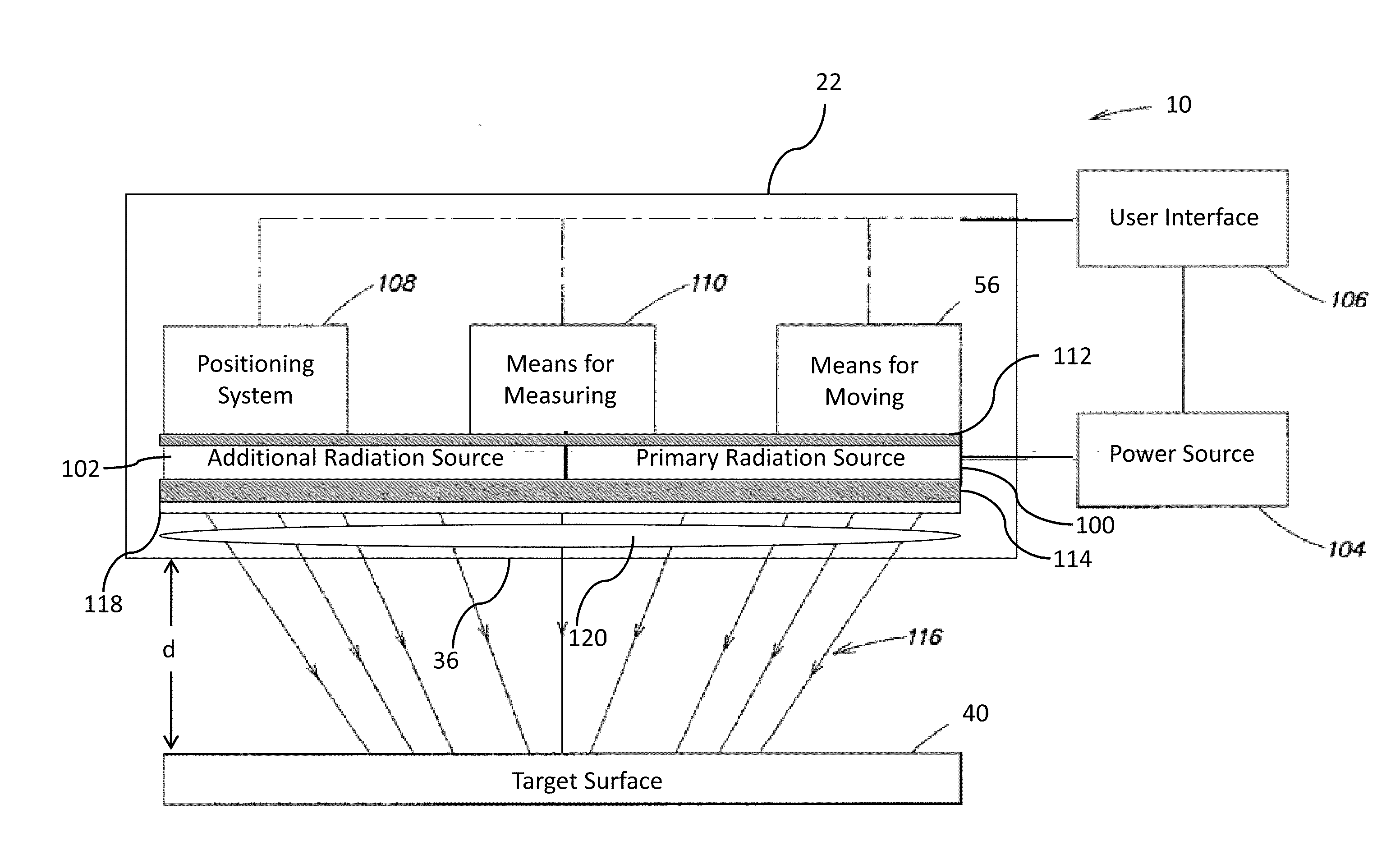
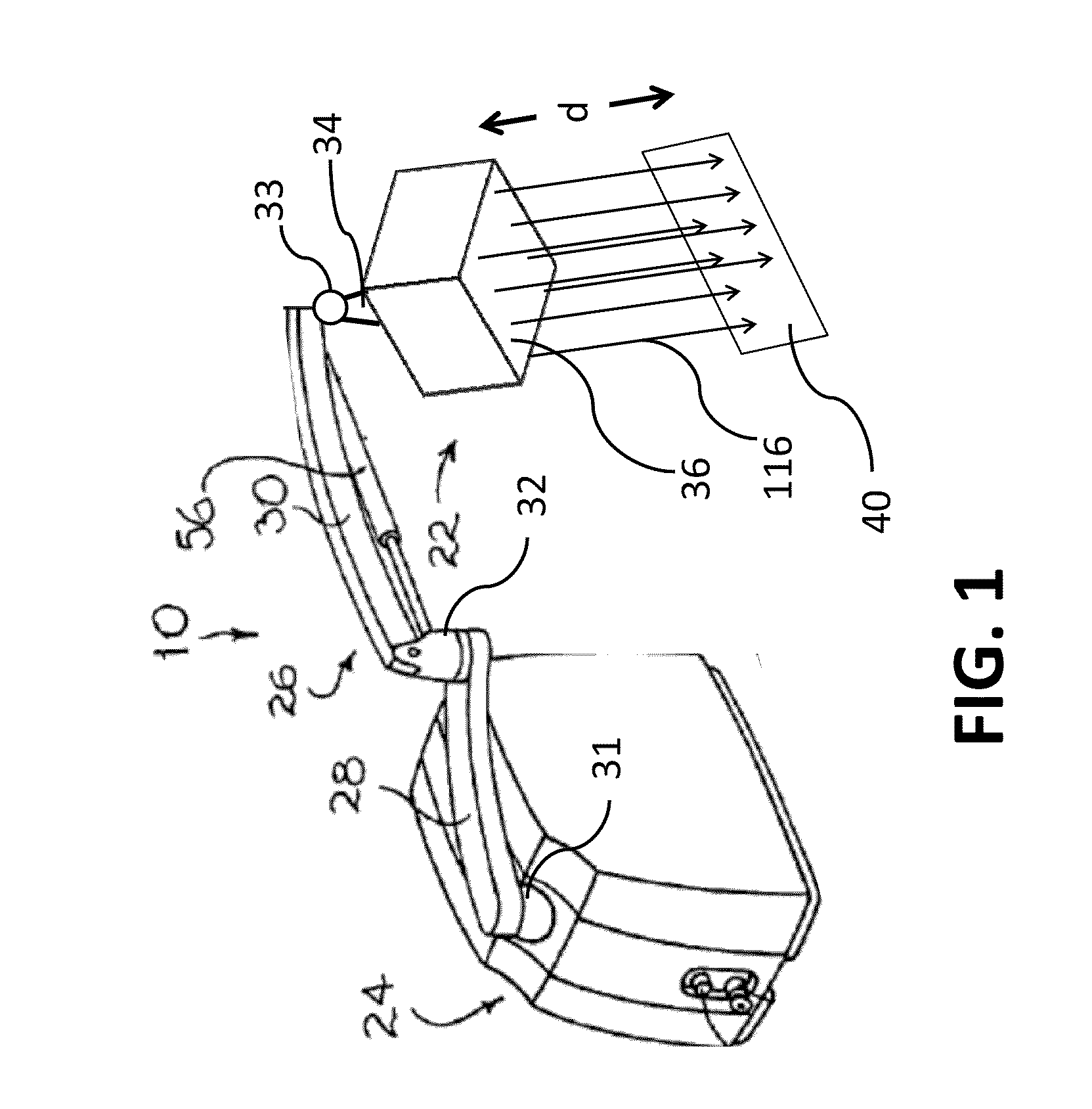
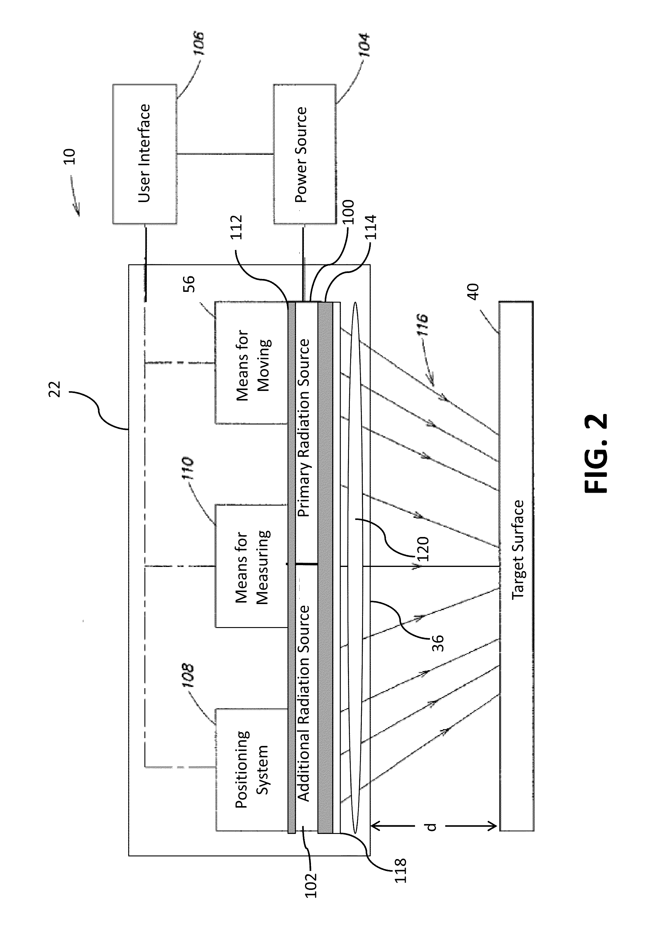
[0021]The present disclosure relates to methods, apparatus, and devices for the controlled application of electromagnetic radiation to a target. Potential uses for embodiments of the present disclosure include, but are not limited to, surface plasmon resonance imaging and therapies, tissue illumination or fluorescence, biological illumination such as to aid in the in vitro growth of cultures, curing systems (e.g. plastics, paint, etc.), plastic molding operations, medical treatments and therapies, and photodynamic therapies. Additional specific medical applications include, but are not limited to, stimulation of new cell growth in wounds, the eradication of pathogenic organisms, and the activation of photosensitive chemicals for the treatment of skin or other cancers. In particular...


PUM


Abstract

Embodiments of this invention relate to a flexible, multifunctional apparatus for delivering electromagnetic energy to a target surface. The apparatus may be used in a variety of applications and environments, including but not limited to, medical therapies and treatments. The apparatus comprises at least one primary radiation source, in some embodiments an array of light-emitting diodes, and is capable of emitting electromagnetic radiation in the range from 800 to 950 nanometers. The apparatus comprises a moveable arm for positioning the radiation source relative to the target surface. The apparatus is useful for photothermal therapy in the treatment of medical conditions, including cancer.

Description

[0001]This application is a non-provisional application of and claims priority to U.S. Ser. No. 61 / 914,786 entitled “Multifunctional Radiation Delivery Apparatus and Method” filed on Dec. 11, 2013, the entire disclosure of which is incorporated herein by reference.FIELD OF THE INVENTION[0002]This invention relates to a flexible, multifunctional apparatus for delivering electromagnetic energy to a target surface. The apparatus may be used in a variety of applications and environments, including but not limited to, medical therapies and treatments. The apparatus comprises at least one primary radiation source, and is capable of emitting electromagnetic radiation in the range from 800 to 950 nm.BACKGROUND OF THE INVENTION[0003]Electromagnetic radiation is known to have many benefits. For example in the area of medical therapies, wavelengths of 680, 730 and / or 880 nanometers have been shown to increase cell growth and speed wound healing (especially when combined with hyperbaric oxygen)...

Claims


Application Information

Patent Timeline
Patent Type & Authority Applications(United States)
IPC IPC(8): G21K5/10A61N5/06A61K51/12A61B18/04
CPCG21K5/10A61B18/04A61N5/0613A61N2005/0642A61B2018/00577A61N2005/0659A61K51/1251
Inventor NAGER, ZACHARY
Owner SIVA THERAPEUTICS
Why Eureka
Try Eureka