Material diagnostic method

Active Publication Date: 2015-06-18
NUCLEAR FUEL INDS +1
View PDF7 Cites 0 Cited by
  • Summary
  • Abstract
  • Description
  • Claims
  • Application Information

AI Technical Summary

Benefits of technology

The present invention provides a method for diagnostics of materials using microstructures of several tens of μm or smaller. This method allows for non-destructive estimation and quantification of materials with high precision regarding their kind, amount of occurrence, depth distribution, and other properties. This enables the diagnosis of materials to be achieved.

Problems solved by technology

The method employing an electron microscope is a destructive technique in which a sample is cut out from the material and then observed by the electron microscope so that the amount of microstructures near the surface is quantified.
Nevertheless, when the depth distribution of the microstructures is to be quantified, problems arise like a large number of samples need be cut out.
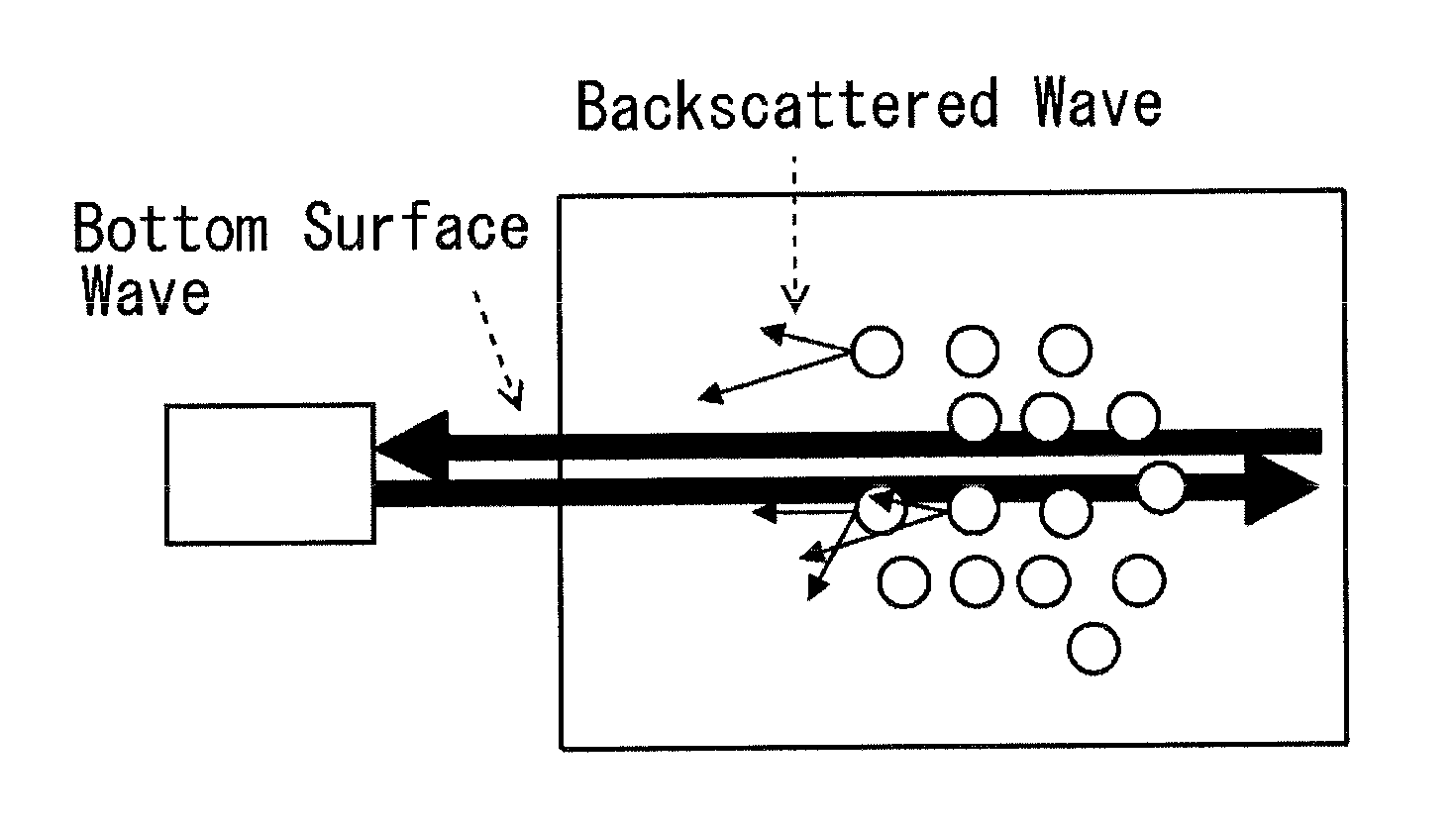
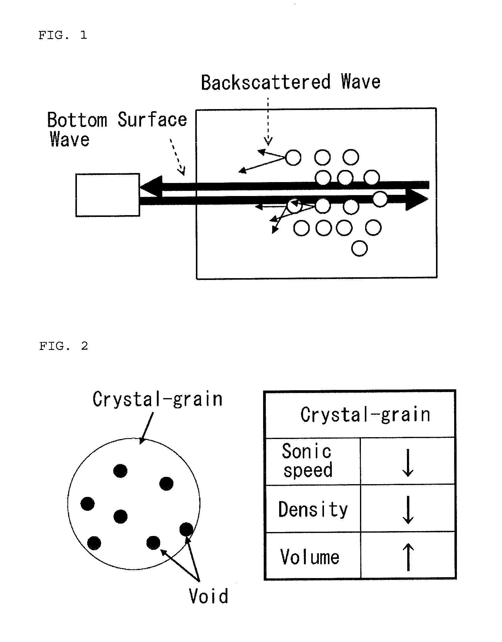
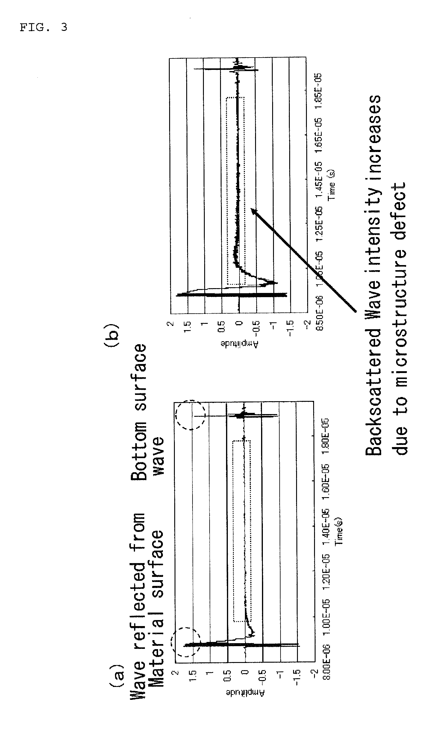
Accordingly, a change in the backscattered wave intensity associated with the occurrence of microstructures is difficult to be identified as a clear signal.
Thus, in a material diagnostic measurement employing ultrasonic of the conventional art, a quantification of these fine microstructure defects has been difficult.
Nevertheless, owing to large errors, quantification has been difficult.

Method used


Image

  • Material diagnostic method
  • Material diagnostic method
  • Material diagnostic method

Examples


Embodiment Construction

1. Quantitative Evaluation of Microstructure Occurrence Amount in Case of Uniform Distribution

[0120]The following description relates to a method of quantitative evaluation of the microstructure occurrence amount in a case that microstructures are distributed uniformly in a material of a hexagonal bar of stainless steel having a thickness of 52.23 mm.

(1) Acquisition of Ultrasonic Data of Material of State without Occurrence of Microstructures

[0121]First, ultrasonic having a peak frequency of 10 MHz was projected into a material (a non-irradiated archive material) of a state without the occurrence of microstructures so that an ultrasonic wave form was acquired.

(2) Acquisition of Ultrasonic Data of Material with Occurrence of Microstructures

[0122]With focusing attention on a change in the physical property value of the crystal grain (a change in the sonic speed was employed here) caused by the occurrence of assumed microstructures, the frequency spectrum was calculated on the basis of...


PUM


Abstract

Provided is a material diagnostic method capable measuring and diagnosing in a nondestructive manner the type, quantity of occurrence, depth distribution, and the like of even very small microstructures of about several tens of μm or less with sufficiently good precision. A material diagnostic method for using ultrasonic waves in a nondestructive manner to diagnose microstructures generated in a material, wherein changes in the scattering of ultrasonic waves by crystal grains are captured from bottom face waves and backscattered waves to thereby quantify the amount of change in microstructures, using the fact that changes in the properties of crystal grains produced by microstructures affect the scattering of ultrasonic waves.

Description

FIELD OF THE INVENTION[0001]The present invention relates to a material diagnostic method of performing non-destructive diagnosis concerning the kind, the amount of occurrence, the depth distribution and the like of microstructures such as precipitates and voids in a steel material such as stainless steel caused by irradiation of radiation, thermal aging, plastic deformation, or the like.BACKGROUND OF THE INVENTION[0002]In the conventional art, as techniques of diagnosing a microstructure change concerning the above-mentioned precipitates, voids, and the like having occurred in the steel material such as stainless steel by means of quantifying the kind, the amount of occurrence, the depth distribution, and the like thereof, techniques have been adopted that employ an electron microscope, ultrasonic, or the like.[0003]The method employing an electron microscope is a destructive technique in which a sample is cut out from the material and then observed by the electron microscope so th...

Claims


Application Information

Patent Timeline
IPC IPC(8): G01N29/36G01N29/11
CPCG01N29/36G01N2291/0234G01N2291/0289G01N29/11G01N29/07G01N29/42G01N29/46G01N2291/044
Inventor ETOH, JUNJISAGISAKA, MITSUYUKIISOBE, YOSHIHIROOKITA, TAIRA
Owner NUCLEAR FUEL INDS
Why Eureka
Try Eureka