System and method of simplifying a direct control scheme for a detector

a direct control scheme and detection system technology, applied in the field of detection systems for use in imaging systems, can solve problems such as the age of sipm, the temperature dependence of the gain of the respective detection element, and the temperature related variation of the gain in imaging applications

Active Publication Date: 2015-06-18
GENERAL ELECTRIC CO
View PDF24 Cites 20 Cited by
  • Summary
  • Abstract
  • Description
  • Claims
  • Application Information

AI Technical Summary

Problems solved by technology

One issue that may arise is, in certain detector technologies where SiPMs are employed, the gain of the respective detection elements may be temperature dependent.
Such temperature related variation in gain may be problematic in imaging applications.
In addition, the SiPM may show temperature sensitivity due to doping variations, or the SiPM may age due to radiation exposure or other affects that can cause gain drift.
Even though temperature is known to be the main cause of SiPM gain drift, those other factors can cause uncertainty or error in knowing the gain of the SiPM, therefore preventing the ability to accurately measure gamma ray energy.
As a result, the temperature sensors do not measure the actual temperature of the SiPM and so drift in gain is typically not accounted for.

Method used


Image

  • System and method of simplifying a direct control scheme for a detector
  • System and method of simplifying a direct control scheme for a detector
  • System and method of simplifying a direct control scheme for a detector

Examples


Embodiment Construction

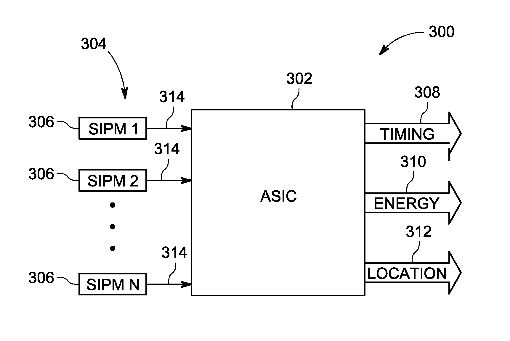
[0020]The operating environment of disclosed examples is described with respect to a PET system, but it is contemplated that the disclosed subject matter may also be useful in other imaging contexts, such as in a SPECT imaging system or in an X-ray based imaging system, such as computed tomography, bone densitometry system. Indeed, the present approach may be employed in conjunction with any nuclear radiation detector that is based on the use of scintillators with a silicon photomultiplier (SiPM) readout.

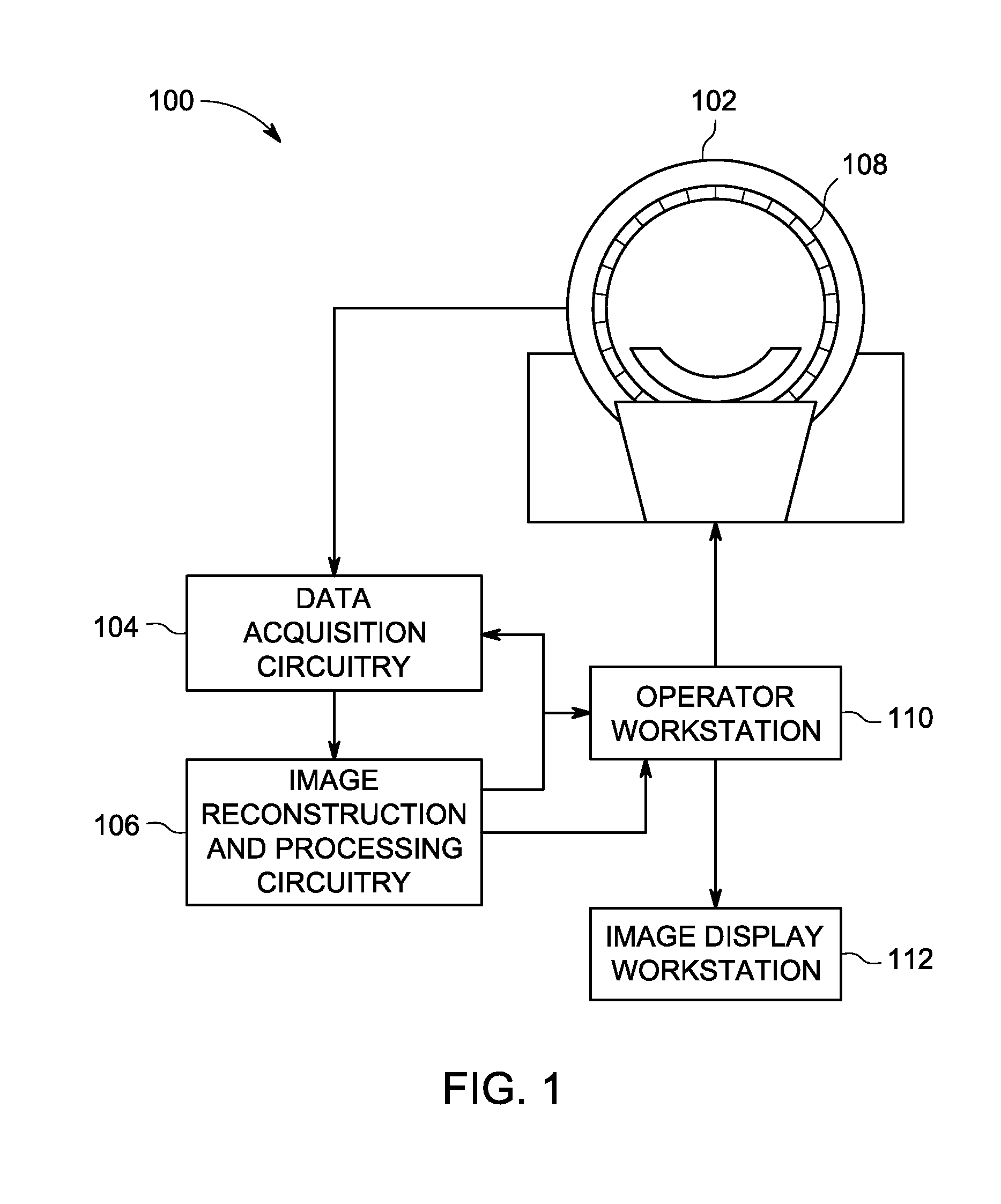
[0021]FIG. 1 depicts a PET system 100 operating in accordance with aspects of the present disclosure. Such a PET system 100 may be used in isolation or in conjunction with another imaging modality, such as a CT or MRI imaging system. PET system 100 includes a detector assembly 102, data acquisition circuitry 104, and image reconstruction and processing circuitry 106. Detector assembly 102 of PET system 100 typically includes a number of detector modules (generally designated by refe...


PUM


Abstract

An imaging system includes a first silicon photomultiplier (SiPM) comprising an array of microcells. Each microcell is an avalanche photodiode (APD) operated in a Geiger mode, a first area of the first SiPM, comprising at least one of the microcells, is electrically isolated from all other microcells, and a signal from the first area, resulting from at least one photon pulse, is used to determine a gain of the first SiPM.

Description

BACKGROUND[0001]The subject matter disclosed herein relates to detection systems for use in imaging systems, such as X-ray based and nuclear medicine imaging systems.[0002]Diagnostic imaging technologies allow images of the internal structures of a patient to be obtained and may provide information about the function and integrity of the patient's internal structures. Diagnostic imaging systems may operate based on various physical principles, including the emission or transmission of radiation from the patient tissues. For example, X-ray based imaging systems may direct X-rays at a patient from some emission source toward a detector system disposed opposite the source across an imaged volume. Attenuation of the X-rays as they pass through the volume, and through any materials or tissues placed between the source and detector, may be determined and used to non-invasively form images of the interior regions of an imaged patient or object. Such attenuation information may be obtained ...

Claims


Application Information

Patent Timeline
Patent Type & Authority Applications(United States)
IPC IPC(8): G01T1/20A61B6/00A61B6/03
CPCG01T1/2006A61B6/585A61B6/037G01T1/208G01T1/248G01T1/20182
Inventor KIM, CHANG L.MCDANIEL, DAVID L.TRAN, VI-HOA
Owner GENERAL ELECTRIC CO
Why Eureka
Try Eureka