Light emitting diode bulb with central axis bidirectional convection heat dissipation structure

a technology of light-emitting diodes and heat dissipation structures, which is applied in the direction of point-like light sources, semiconductor devices of light sources, lighting and heating apparatus, etc., can solve the problems of significant reduction in the service life of led bulbs, bulb structure complexity, and inability to sell to ordinary consumers, so as to effectively avoid user burns and thermal conductivity

Inactive Publication Date: 2015-06-25
SKYNET ELECTRONICS
View PDF6 Cites 22 Cited by
  • Summary
  • Abstract
  • Description
  • Claims
  • Application Information

AI Technical Summary

Benefits of technology

[0015]It is an objective of the present invention to provide an LED bulb with a central axis bidirectional convection heat dissipation structure. The LED bulb includes a lower cover, a separating unit, a heat sink and an upper cover. The lower cover is made of a non-thermally conductive or insulating material and is provided with a bulb socket on the outer bottom side of the lower cover. The lower cover is provided therein with a driving circuit board near the bottom side thereof, wherein the two electrodes of the bulb socket are separately and electrically connected to the driving circuit board, the outer periphery of the lower cover is provided with at least one ventilation hole so as to allow inside and outside of the lower cover to communicate with each other through the ventilation hole, and the top side of the lower cover is formed with a first coupling opening. The separating unit has a bottom side provided within the lower cover at a position between the lower edge of the ventilation hole and the driving circuit board, so as to confine the driving circuit board within the lower cover at a position near the bottom side of the lower cover, and a top side provided within the lower cover at a position between the upper edge of the ventilation hole and the first coupling opening, wherein the separating unit is formed with at least one convection pathway which can communicate with the top side of the separating unit and the ventilation hole, respectively. The heat sink is made of a thermally conductive material having a thermal conductivity coefficient higher than that of non-thermally conductive or insulating material, wherein the bottom end of the heat sink is position

Problems solved by technology

However, since the LED itself generates a non-negligible amount of heat during illumination, if an LED bulb cannot properly dissipate the massive amount of heat generated by the LEDs therein, the temperature of the LEDs will then be raised up to and stay at a very high level.
A sustained high temperature can cause the materials of the LEDs to age prematurely, cause the LEDs to undergo luminous decay, and consequently cause a significant reduction in service life of the LED bulb.
However, most of the newly designed LED bulbs still have very complicate structures and can only be manufactured at very high costs which cause the selling prices thereof are unacceptable to ordinary consumers.
As the temperature of the LEDs A131 increases and heat accumulates on the heat dissipating fins A102, the tem

Method used


Image

  • Light emitting diode bulb with central axis bidirectional convection heat dissipation structure
  • Light emitting diode bulb with central axis bidirectional convection heat dissipation structure
  • Light emitting diode bulb with central axis bidirectional convection heat dissipation structure

Examples


first embodiment

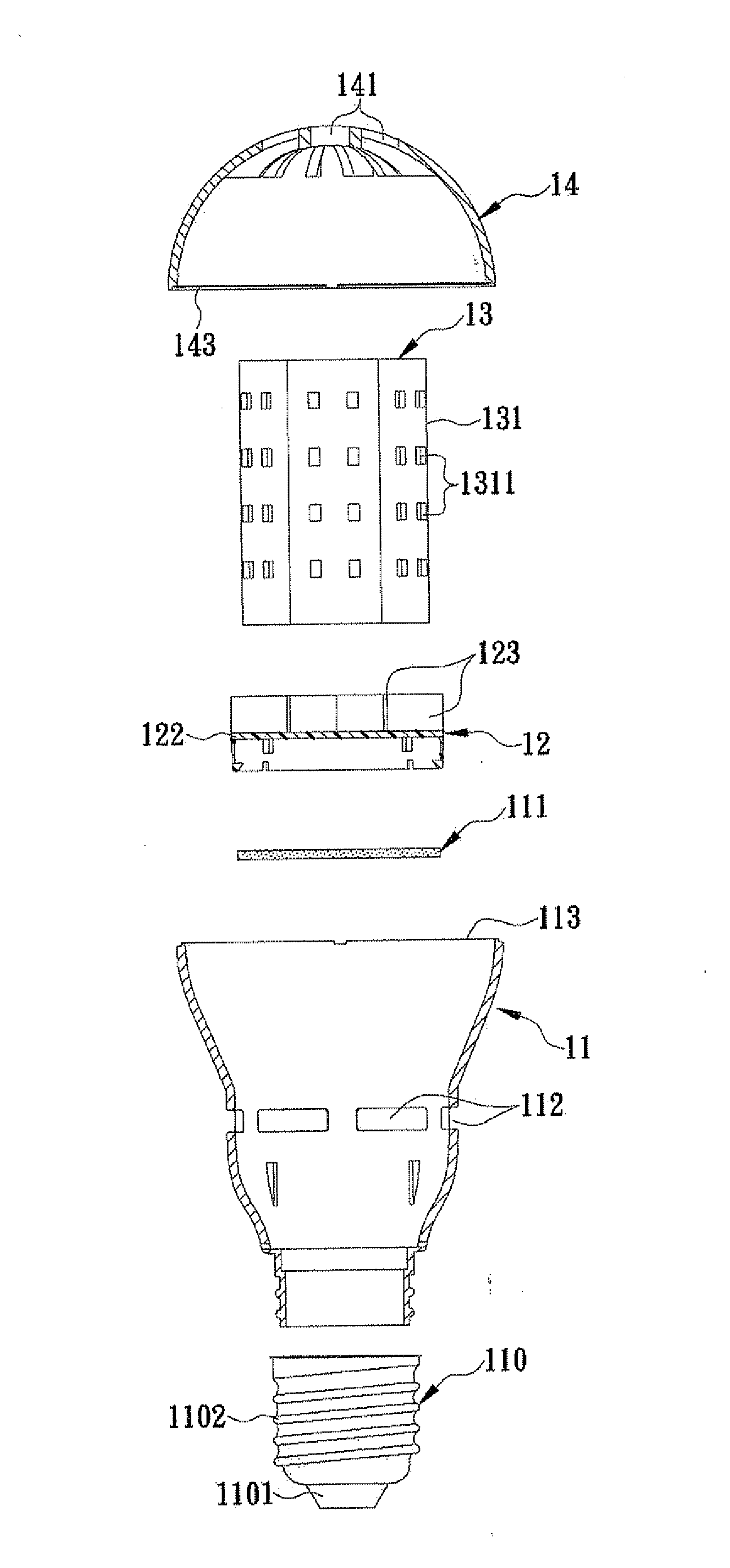
[0029]Again referring to FIGS. 4 and 5, the heat sink 13 in the first embodiment is made of a thermally conductive material having a thermal conductivity coefficient higher than that of non-thermally conductive or insulating material. The bottom end of the heat sink 13 is positioned on the top side of the separating unit 12 such that the heat sink 13 can be in communication with the ventilation hole 112 through the convection pathway 121. There is at least one LED circuit board 131 attached to the outer side of the heat sink 13, wherein the LED circuit board 131 is electrically connected to the driving circuit board 111 so as to receive the driving power transmitted from the driving circuit board 111 and drive at least one LED 1311 on the LED circuit board 131 to emit light. The upper cover 14 is made of a light permeable material, and has a top side formed with at least one convection hole 141. The top end of the heat sink 13 is positioned in the upper cover 14 and corresponds in p...

second embodiment

[0034]Again referring to FIG. 8, the bottom end of the heat sink 23 in the second embodiment is positioned on the top side of the second separating plate 223 and corresponds in position to the penetrating hole 2231 such that the central axis hole 232 in the heat sink 23 can communicate with the ventilation hole 212 through the penetrating hole 2231. The outer side of the heat sink 23 is attached with at least one LED circuit board 231, wherein the LED circuit board 231 is electrically connected to the driving circuit board 211 so as to receive the driving power transmitted from the driving circuit board 211 and drive at least one LED 2311 on the LED circuit board 231 to emit light. The top side of the upper cover 24 is formed with at least one convection hole 241. The top end of the heat sink 23 is positioned in the upper cover 24 and corresponds in position to the convection hole 241 such that the central axial hole 232 in the heat sink 23 is able to communicate with the cold ambie...


PUM


Abstract

An LED bulb includes a lower cover having ventilation holes formed at outer periphery thereof, and a first coupling opening formed at top side thereof; a separating unit provided within the lower cover at a position between lower edges of the ventilation holes and bottom side of the lower cover, and having a convection pathway formed at top side thereof; a heat sink having bottom end positioned on top side of the separating unit; and an upper cover having top side formed with convection hole corresponding to top end of the heat sink, and a second coupling opening formed at bottom side thereof. When the second and first coupling openings are coupled with each other, the upper and lower covers are assembled together to form a central axis bidirectional convection heat dissipation pathway sequentially through the ventilation hole, the convection pathway, the heat sink and the ventilation hole accordingly.

Description

FIELD OF THE INVENTION[0001]The present invention relates to a light emitting diode (hereinafter referred to as LED) bulb, more particularly to an LED bulb having a simplest structure along with a central axis bidirectional convection heat dissipation pathway formed therein, so that the LED bulb can be manufactured at a lowest cost and the massive amount of heat generated by LEDs inside the LED bulb can be quickly exchanged with cold ambient air outside the LED bulb through the heat dissipation pathway both in ways of thermal conduction and thermal convection, thereby effectively lower the temperature of the LEDs as well as effectively reducing luminous decay of the LEDs and extending the service life of the LED bulb. Moreover, since heat sink structure provided on the heat dissipation pathway is fully enclosed in the LED bulb, the LED bulb can keep the heat sink structure from being inadvertently touched by a user and effectively prevent the user from being burned.BACKGROUND OF THE...

Claims


Application Information

Patent Timeline
IPC IPC(8): F21V29/00F21V23/00
CPCF21V29/2268F21Y2101/02F21V29/004F21V23/005F21S2/00F21V23/003F21Y2101/00F21V29/503F21V3/02F21V17/002F21V19/004F21V29/506F21V29/83F21K9/23F21Y2115/10F21Y2107/40
Inventor LIANG, JIM-HUNG
Owner SKYNET ELECTRONICS
Why Eureka
Try Eureka